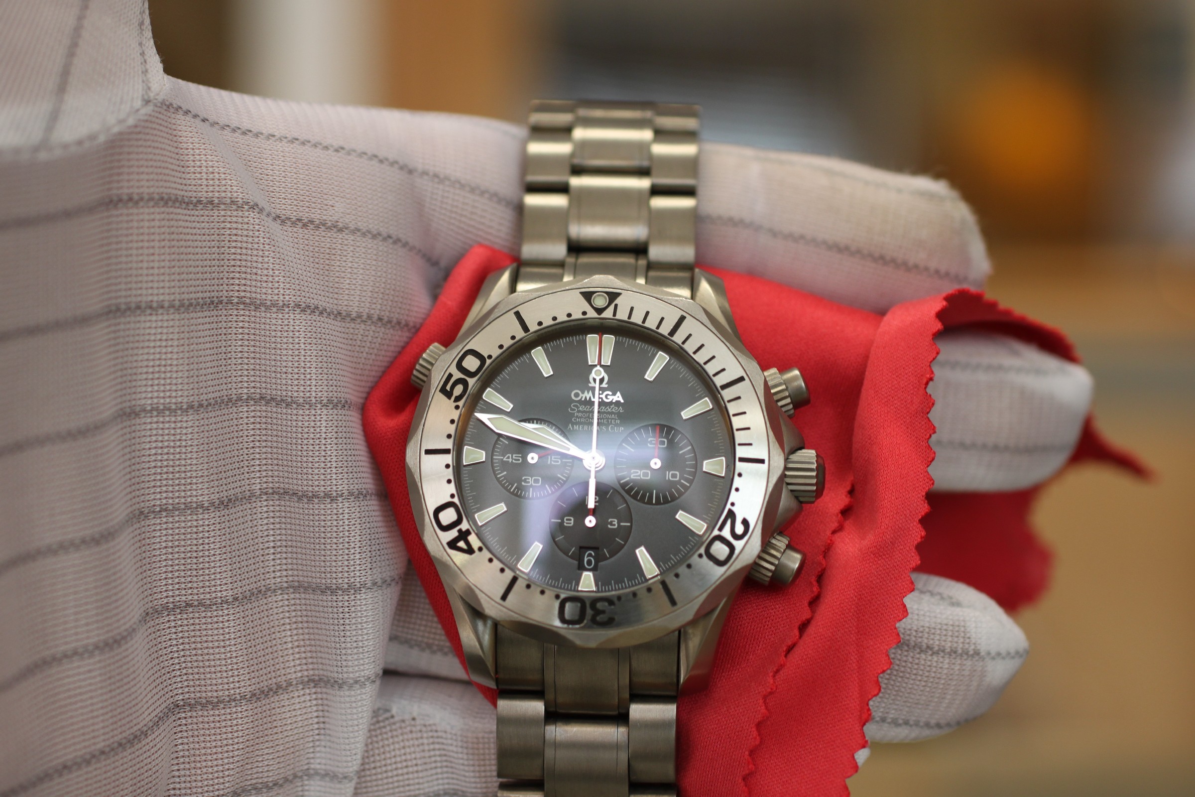
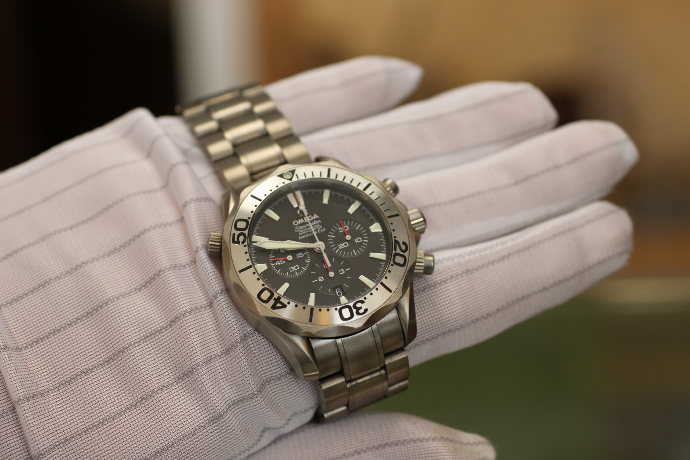
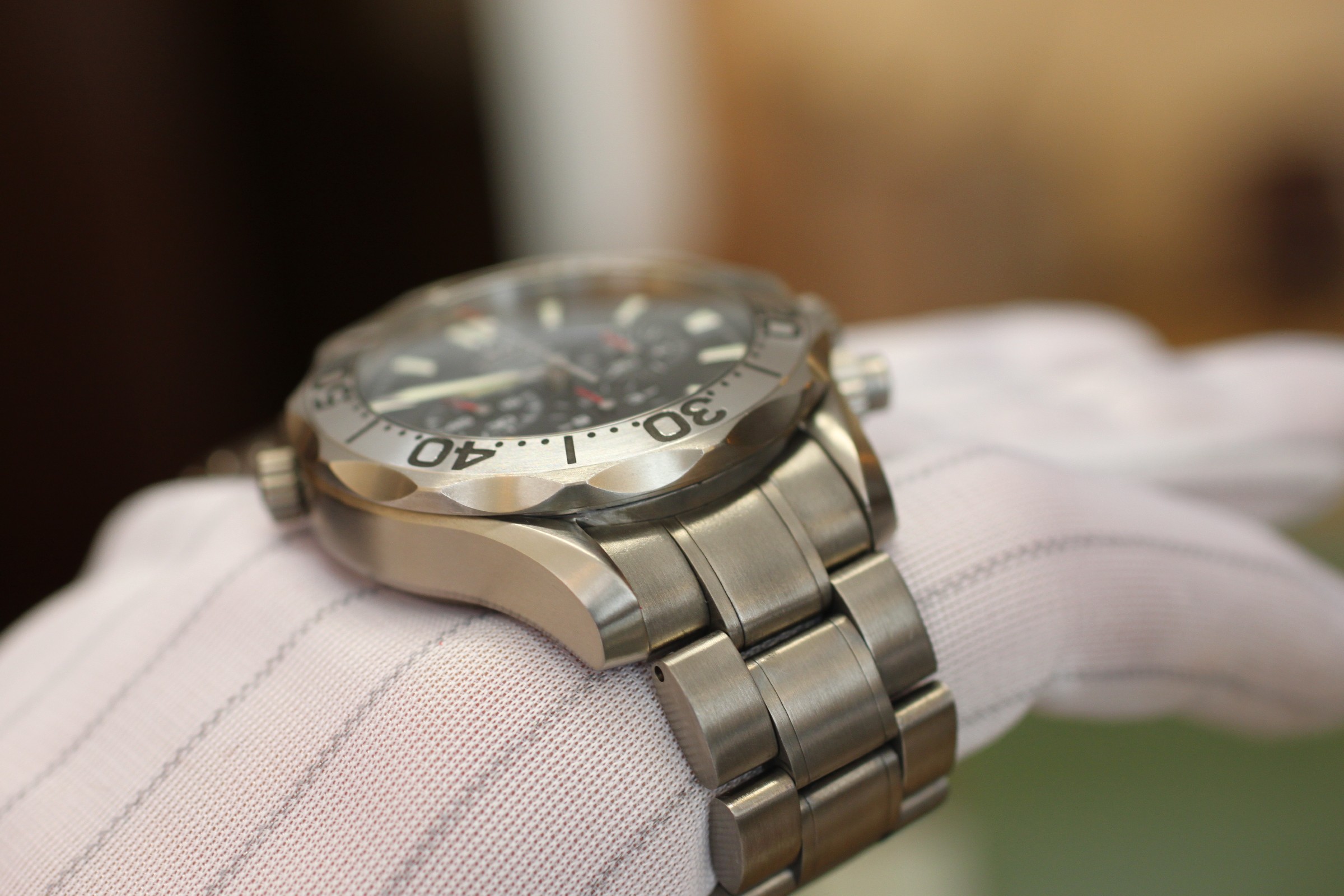
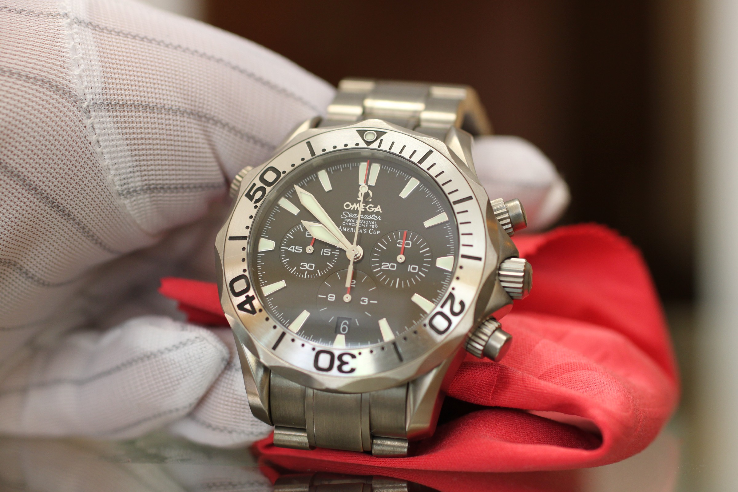
Repairing an Omega 3303 chronograph
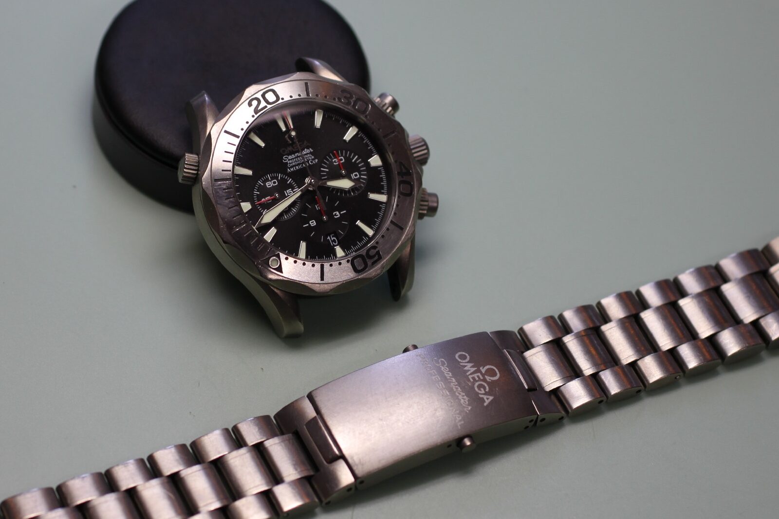
Ref. 178.0515
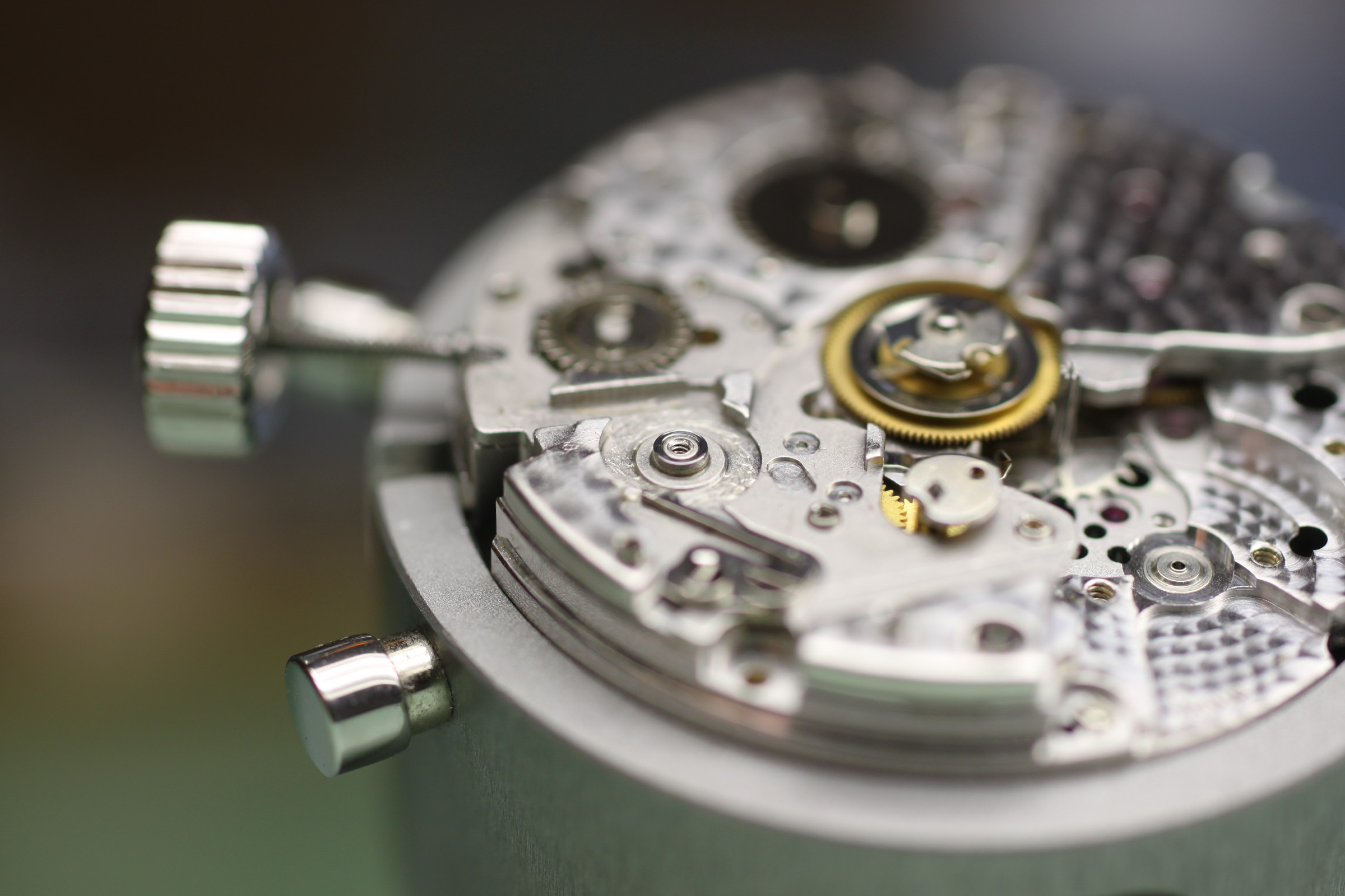
Omega calibre 3303 shares its construction with Omega calibre 3313, but has a Swiss lever escapement instead of the Co-Axial escapement. There are further Omega variants, such as calibre 3612 with split-seconds chronograph or 3603 with GMT.
Less well known is that this movement is among the most commonly used chronograph movements of all, used even more frequently in the luxury segment than the familiar Valjoux 7750. Originally introduced by Frédéric Piguet in 1987 as the manually wound calibre 1180, this extremely thin calibre quickly found its way into many watches from various brands. Also produced as the automatic 1185 and the split-seconds 1181 and 1186, it was first used by Blancpain as the F185. Further top-tier brands used it as Breguet 576, Vacheron Constantin 1137 or 1136 QP (perpetual calendar), Audemars Piguet 2385, Cartier 1904 and Jaeger-LeCoultre 751 or 752; a more distant relative with clear similarities is Piaget 880P (two barrels).
One version is made exclusively for Omega and designated Frédéric Piguet 1285 or Frédéric Piguet 1286.
For this Omega, the case is to be refreshed alongside a complete movement service.
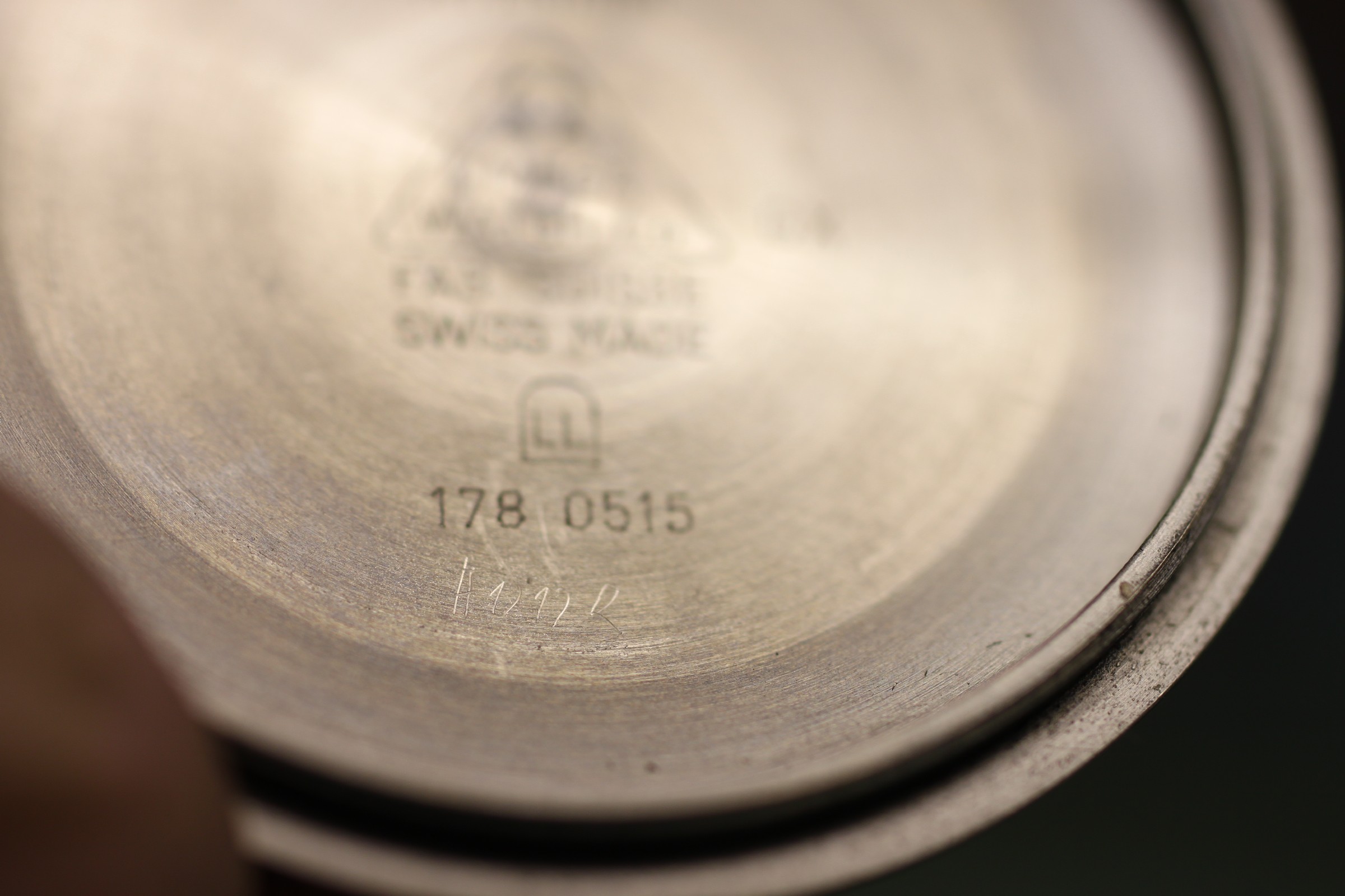
The previous service did not leave a convincing impression. The watchmaker even scratched something into the case back.
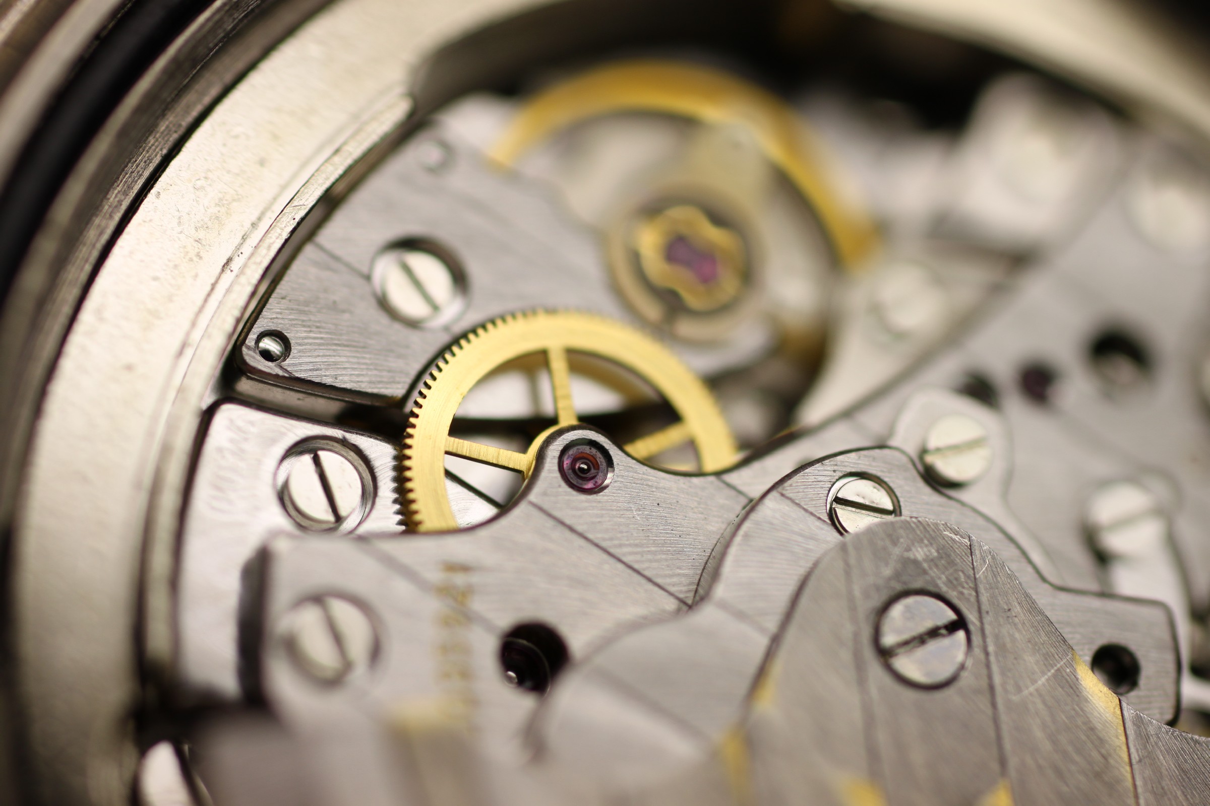
The screw slots in the photographs also show that an incapable watchmaker has left traces here at least once. Unfortunately, this is still the case in a very large proportion of all movements.
The spread-out oil drop in the shock protection is immediately visible here. This happens either because the cap jewel was inadequately cleaned or because the quantity or placement of oil is wrong.
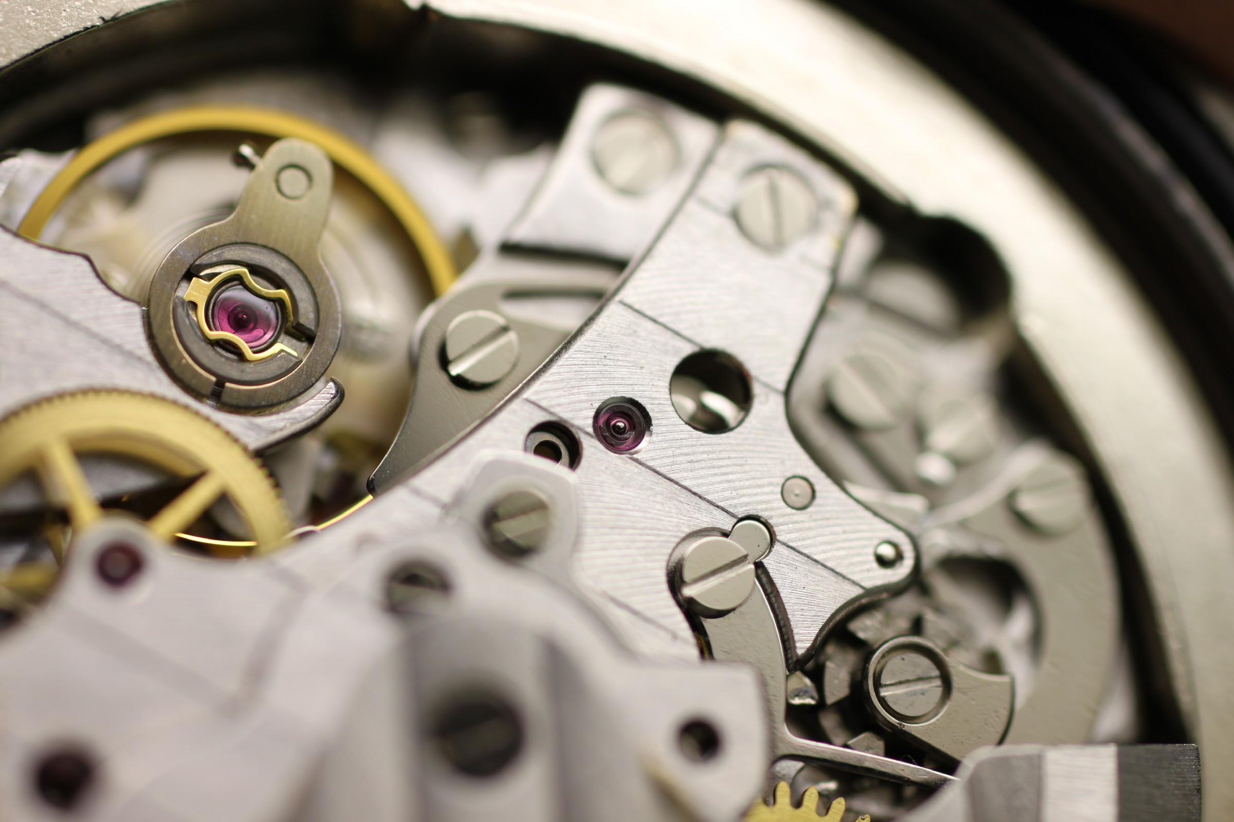
The jewel on the right (hour counter) should also not be lubricated, particularly not on the visible end face. An unclean stake was used for support here when fitting the hands.
The same picture appears below at the fourth-wheel jewel.
The golden traces on the rotor are bare brass. The plated layer (usually nickel plating), together with part of the decorative finish, has been rubbed away as the rotor scraped against the dust cover. The metal dust has spread through the movement and collects particularly in the oiled bearings. The watch should not continue running like this: another reason for a service.
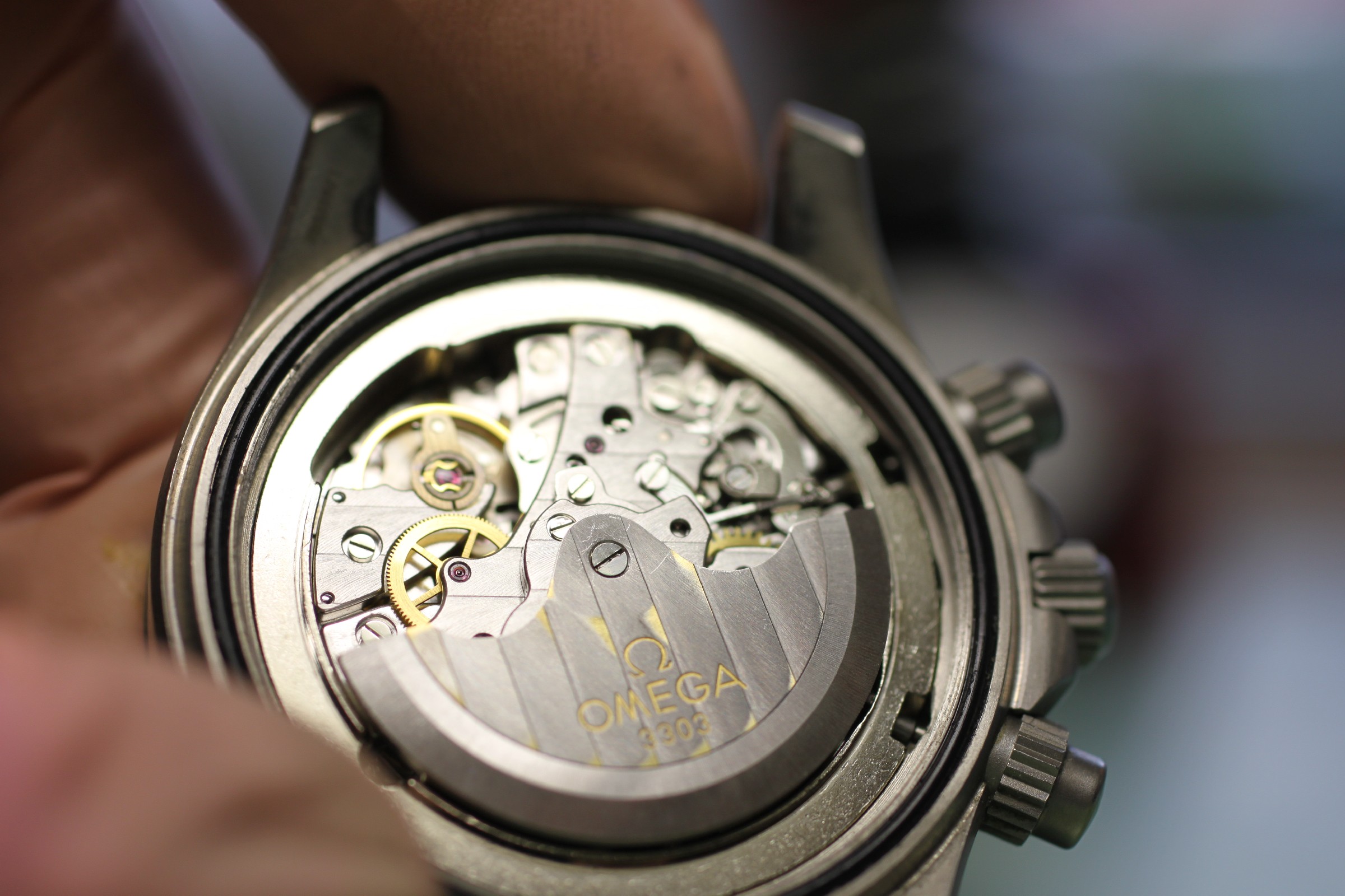
This is a common fault caused by excessive rotor endshake. Once its cause has been corrected, however, there is no technical reason not to continue using the rotor. This spare part does, after all, cost a three-figure sum.
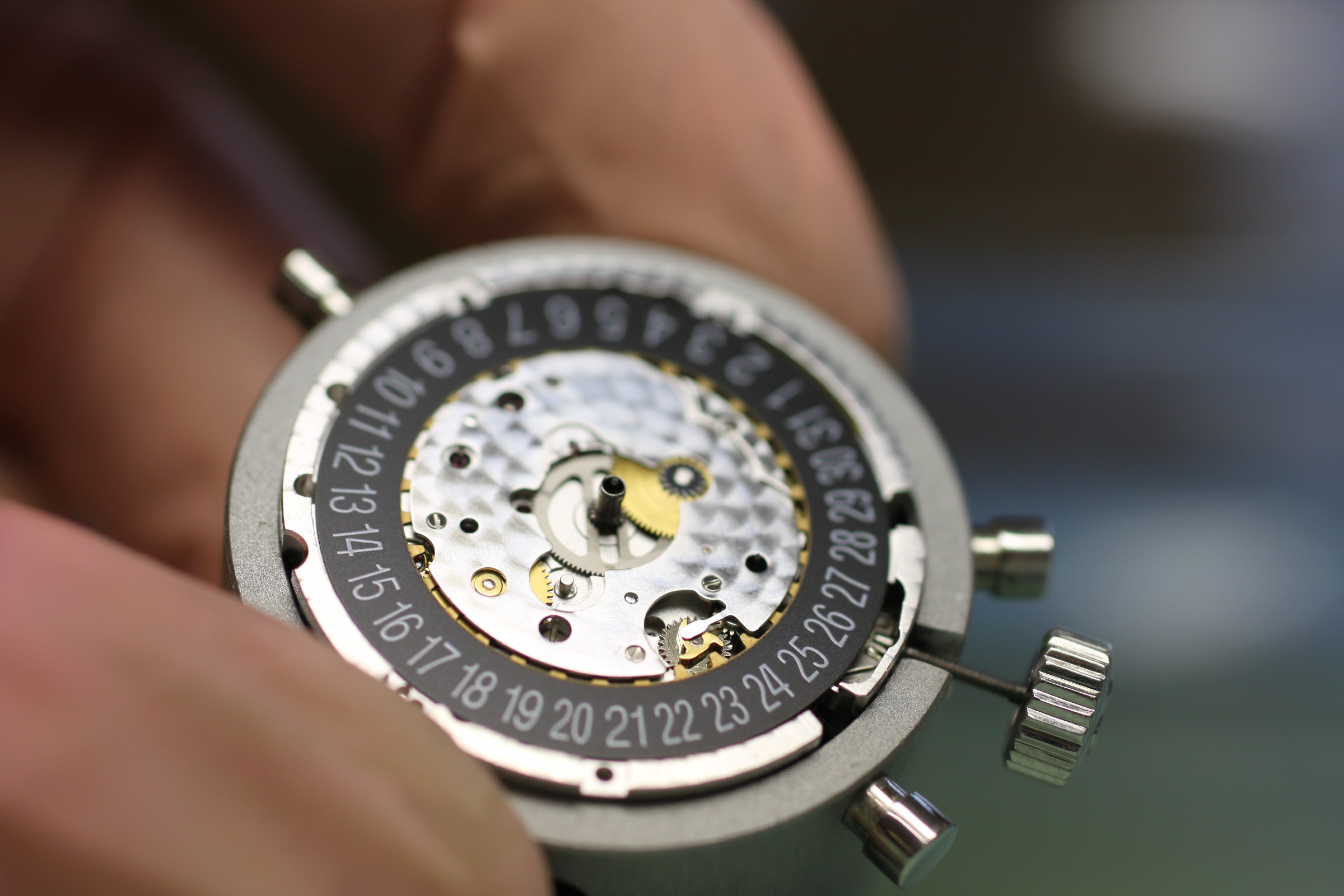
The dial and hands, by contrast, are in excellent condition. The date mechanism is visible beneath the dial.
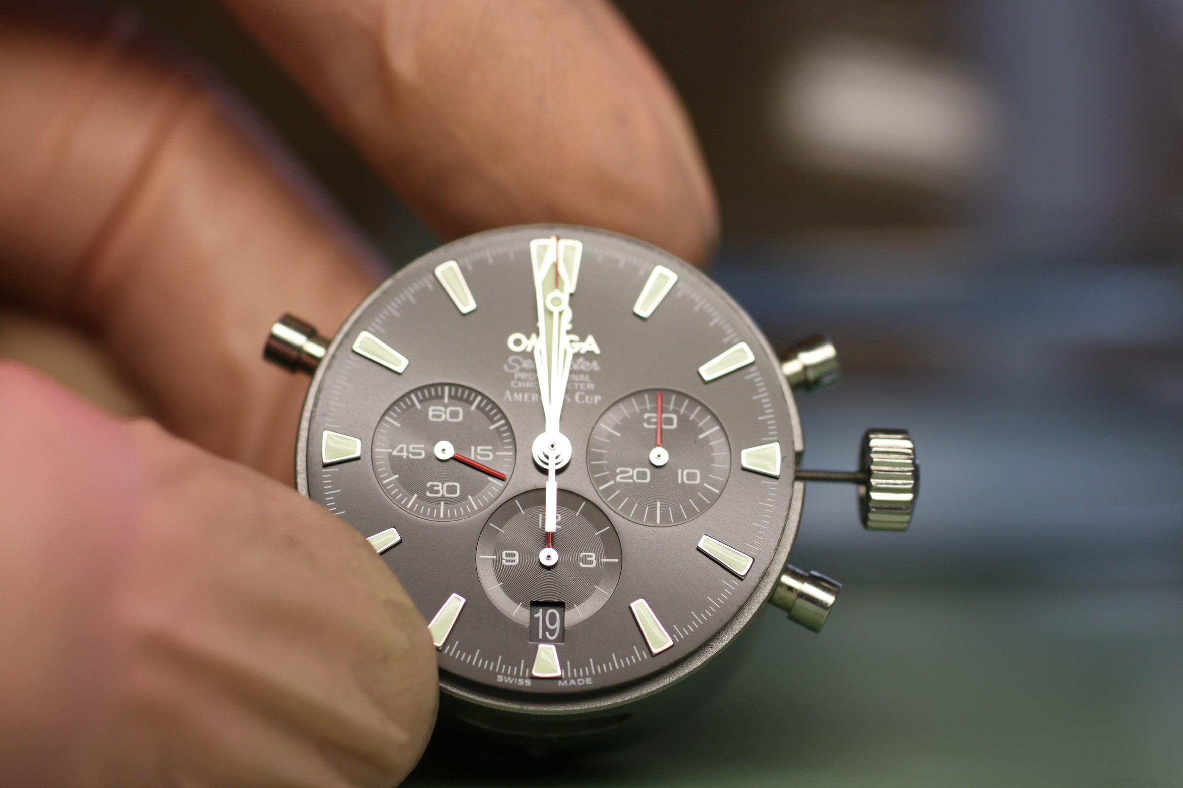
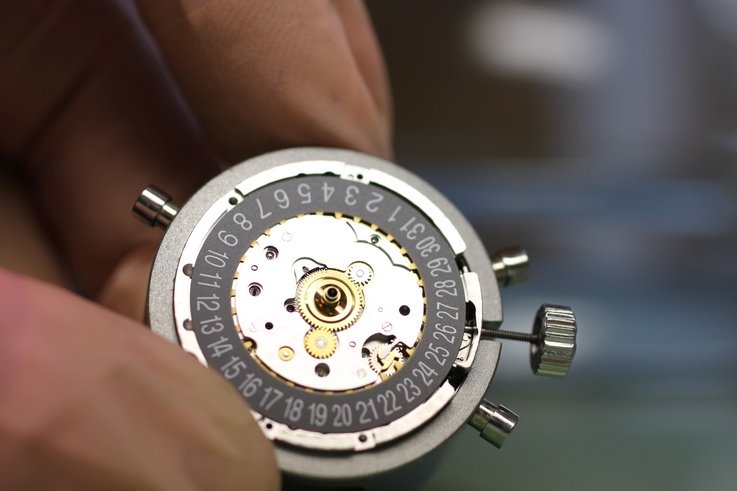
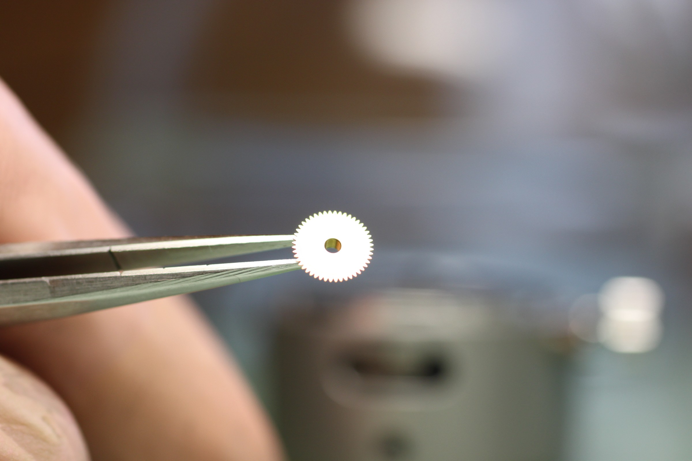
The hour wheel in the penultimate photograph should always be examined from underneath. If the contact surface between the cannon pinion and hour wheel shows wear marks running radially rather than in a circle, it should be replaced. After this brief check, we return to the movement side.
Substantial endshake is clearly visible here. An ideally small endshake would not have been visible in the photographs.
The next photograph shows the wheels beneath the automatic bridge, into which the rotor ball bearing is firmly riveted.
The automatic winding components. The slots for the rocking pinion tend to wear. During assembly, Omega’s lubrication chart should be followed precisely: too much oil, or oil in the wrong place, results in low winding force from the automatic system.
The components in this photograph show that the watch has not run very much.
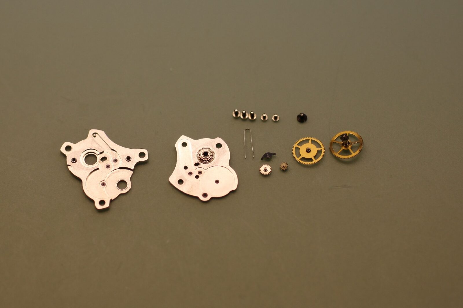
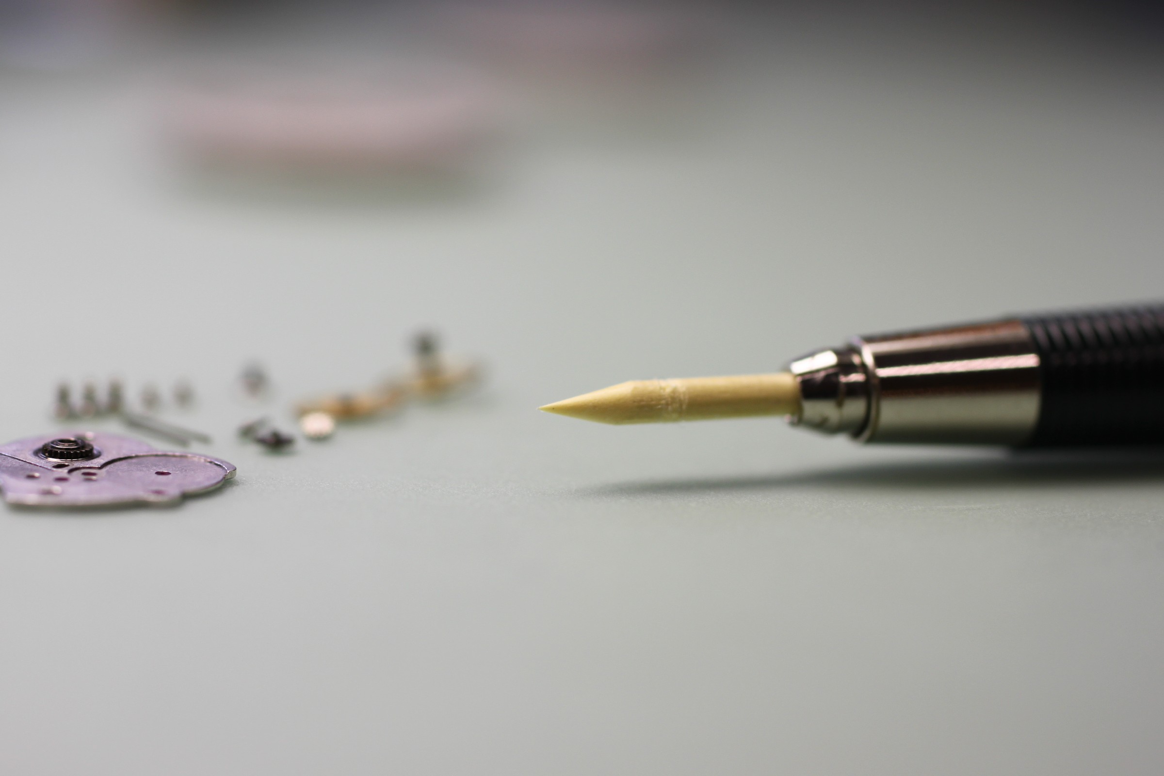
Even in watches with little contamination, all bearings should be cleaned from above and below with pegwood.
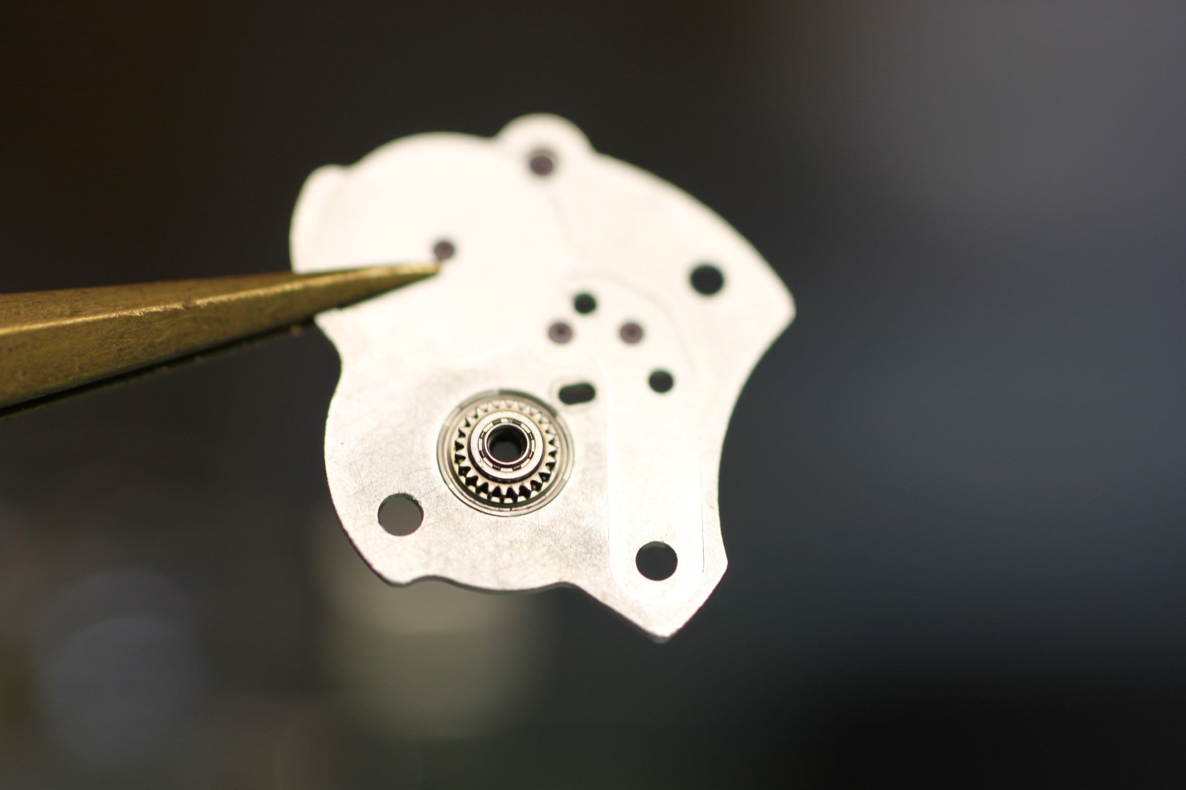
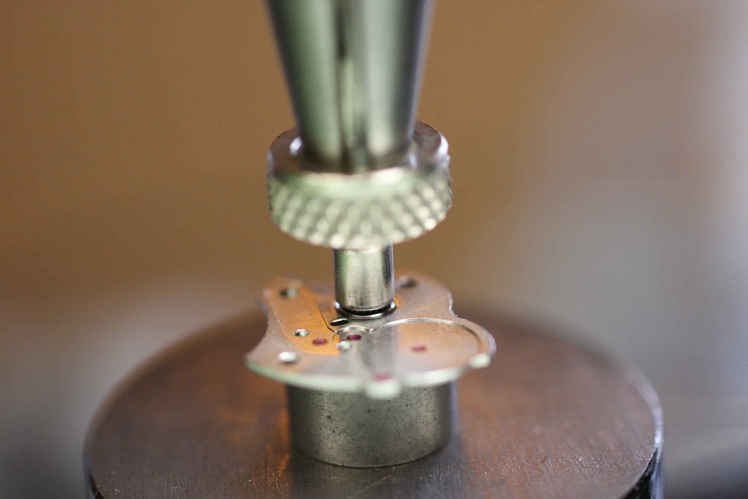
The endshake of the ball bearing in this version can be adjusted with the appropriate pressing stakes. If small laser welds are visible on the underside, however, the endshake cannot be adjusted. The lower stake is flat; the upper stake presses the lower bearing race, with its attached pinion, downwards in a ring.
Movement Detail 1
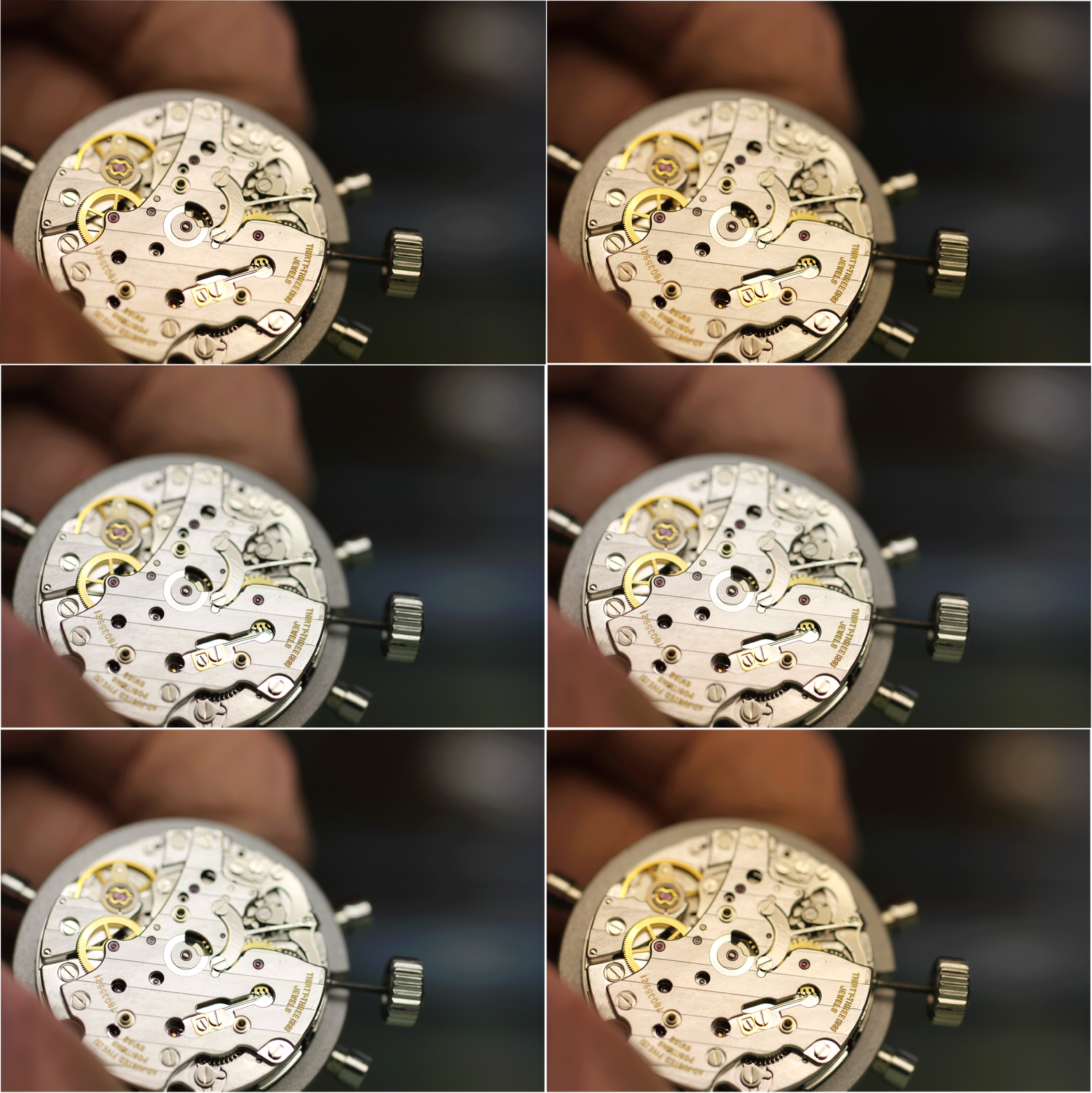
Among other things, the action of the finger on the central chronograph runner, which operates the minute-counter transmission wheel, must be checked closely.
The endshake must not allow the advancing finger to pass underneath or above the transmission wheel.
The action must also advance the minute-counter wheel cleanly by exactly one tooth (only slight contact of the finger with the next tooth of the transmission wheel immediately after advancing is permitted – WITHOUT deflecting the minute-counter wheel again).
Movement Detail 2
The hour-counter wheel must have no play when the chronograph mechanism is reset to zero. Otherwise, the hour-counter hammer is bent or damaged. The hour-counter heart has a small hole into which a fine oiler can be carefully inserted to „wiggle it“ . It must not move during this check.

Movement Detail 3
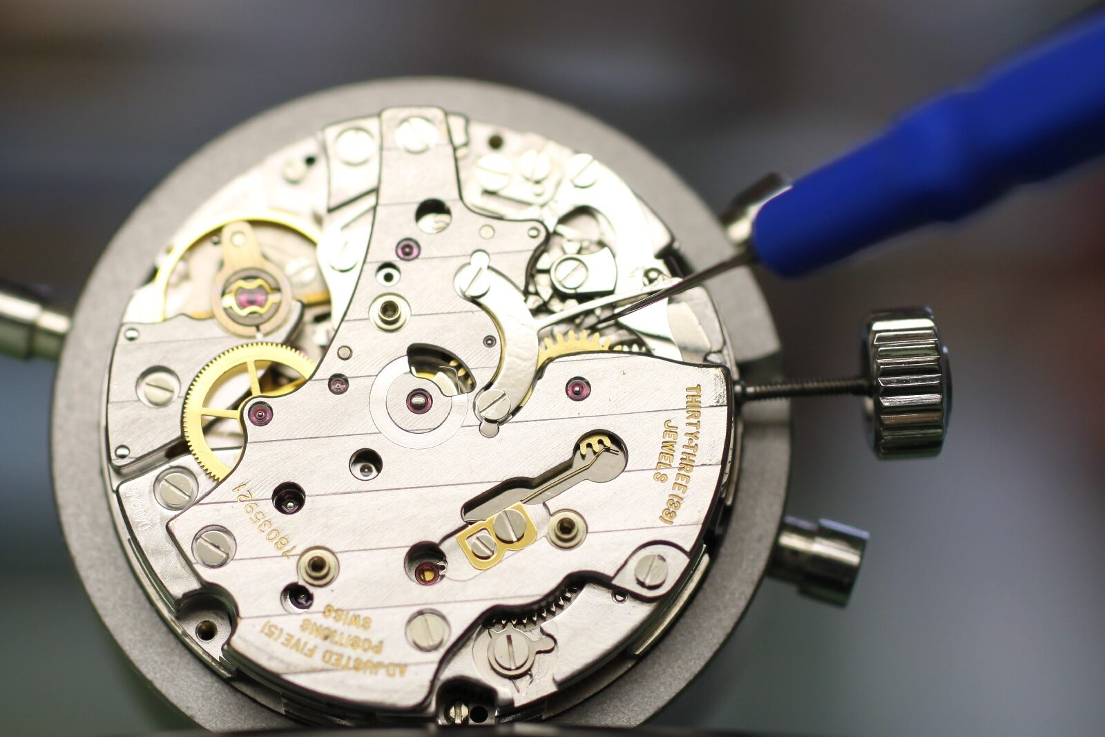
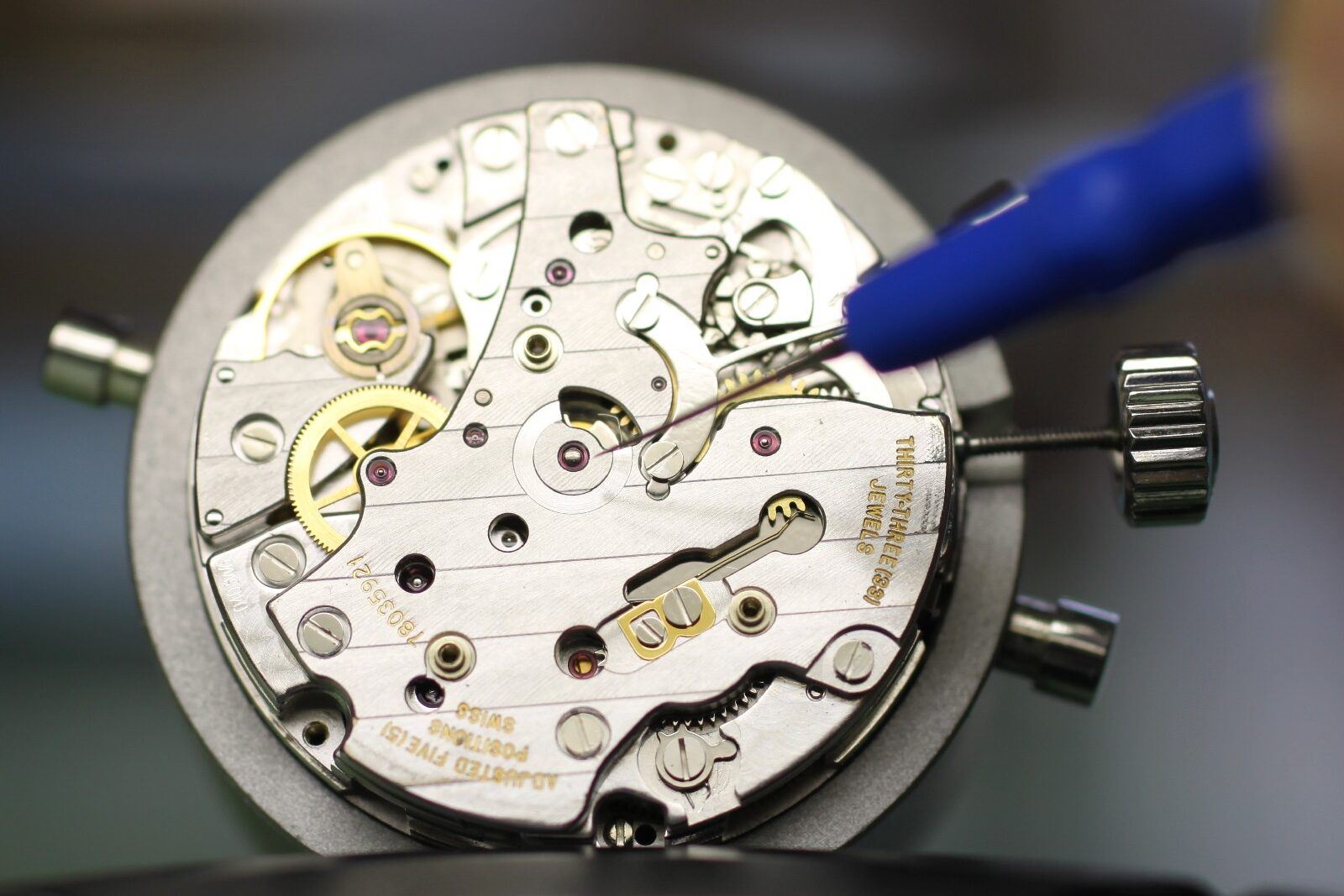
The operating nose of the start/stop lever must engage precisely with the column wheel. The lever tends to bend and then often only just engages with the column wheel, tip to tip. In this case, the instructions require replacement of the lever, not straightening. A detailed view of the lever in operation, with another important check, follows later.
Movement Detail 4
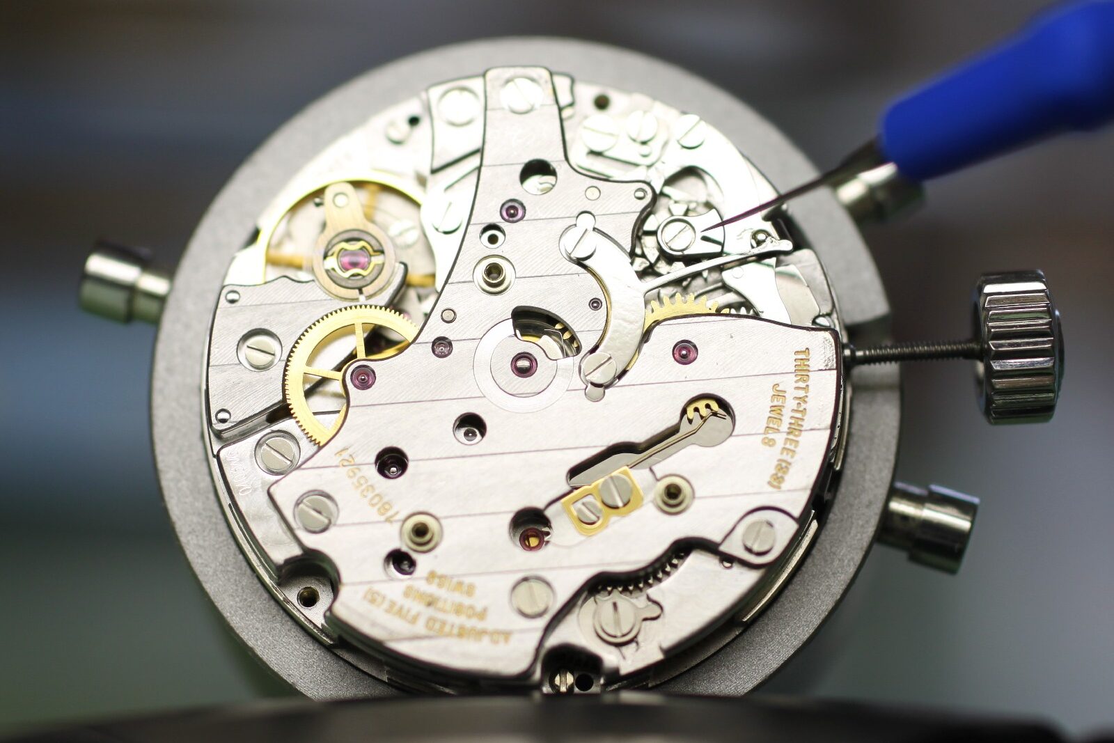
The lower edge of the column-wheel bridge should be positioned exactly parallel to the operating arm of the start/stop lever, then screwed down. (Here it is rotated a little too far clockwise.
Movement Detail 5
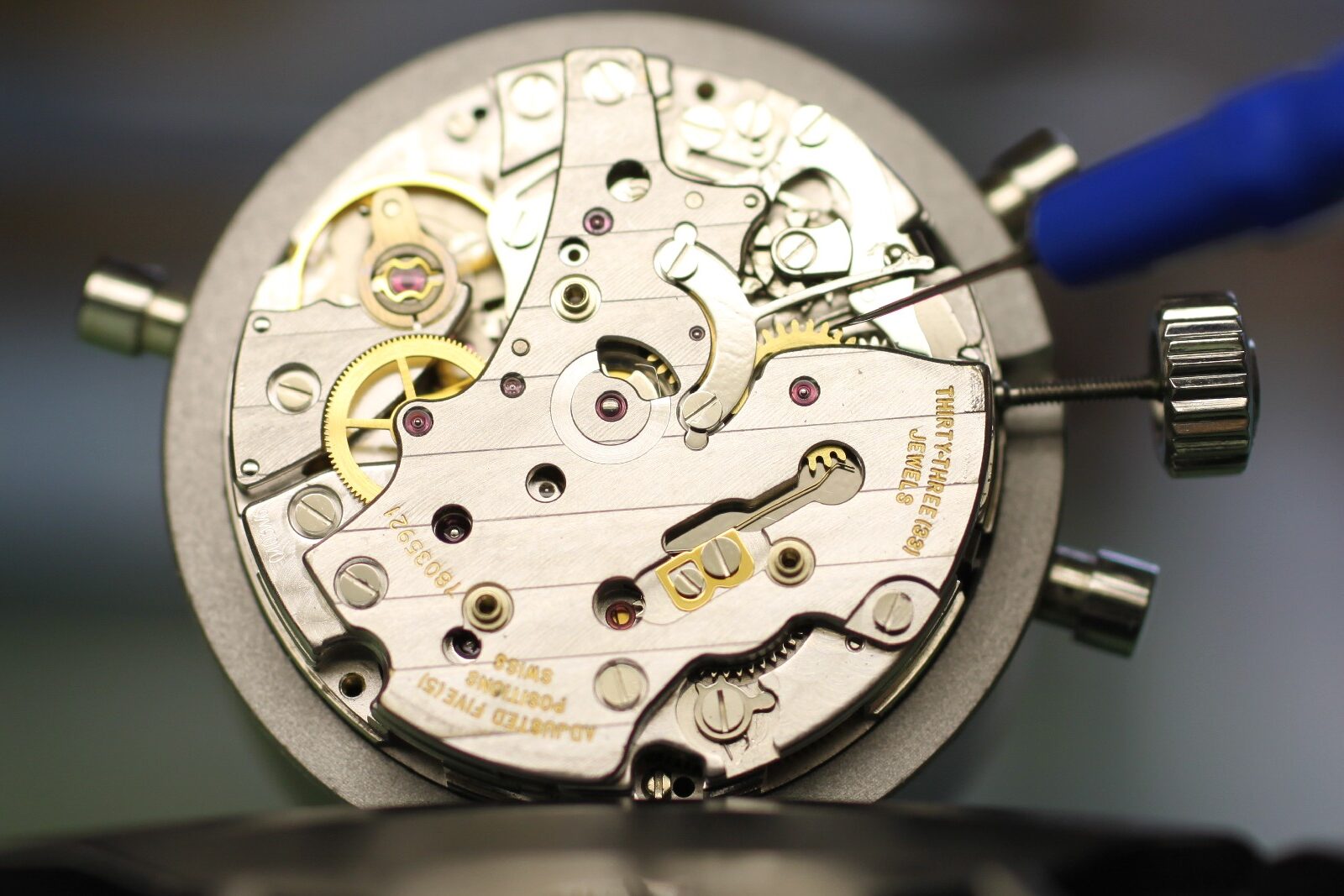
With the chronograph running (the wrong photograph is shown here), the minute-counter wheel must be advanced through a full cycle without the finger of the central chronograph runner engaging with the transmission wheel. In the cleaned condition, every tooth must advance cleanly. If not, either the tension of the minute-counter jumper (the golden spring) must be increased, or the cause of the minute counter’s high resistance to rotation must be found.
Movement Detail 6
Back in the reset position, the minute counter is deflected first in one direction and then the other to assess the play between the hammer and the heart of the minute-counter wheel. The play should be as equal as possible on both sides (the position is adjustable by a screw and eccentric) and must under no circumstances be so large that the jumper can pass over a tooth tip. If this happens, the stop lever is often bent or damaged.
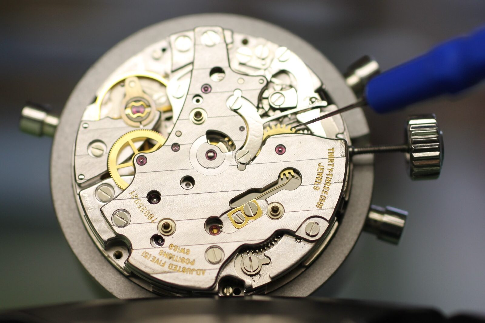
Movement Detail 7
In the fault mentioned above, the barrel bridge is sometimes also damaged – : a strong impact on the start/stop lever can occasionally cause it to strike the bridge hard enough to notch it at the contact point. This notch causes the bridge to bulge slightly above that point. Unfortunately, this bulge is in the sliding surface of the hammer, which can then be partially obstructed – and no longer resets cleanly to zero. The bridge can often be saved by simply pressing it back with a flat stake.
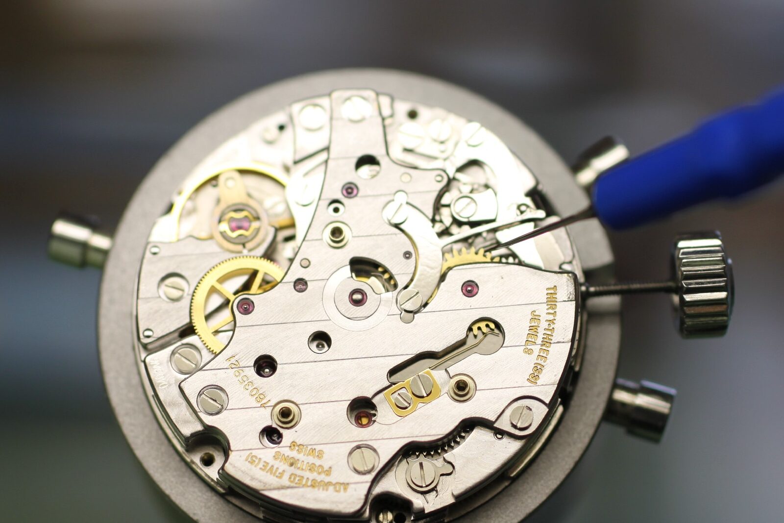
Movement Detail 8
With the chronograph running, the external endshake of the central chronograph runner can be checked. It should be very small, as the wheel can easily contact other parts at various points. Excessive endshake also encourages the previously mentioned finger to pass below or above the transmission wheel.
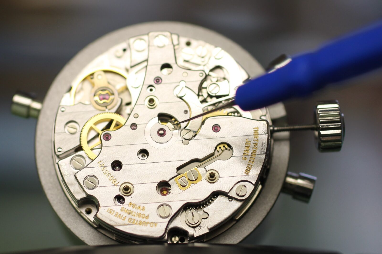
Movement Detail 9
If a bent start/stop lever prevents operation for testing the chronograph, the operating arm can be nudged gently into position during switching. Take care not to scratch the bridge.
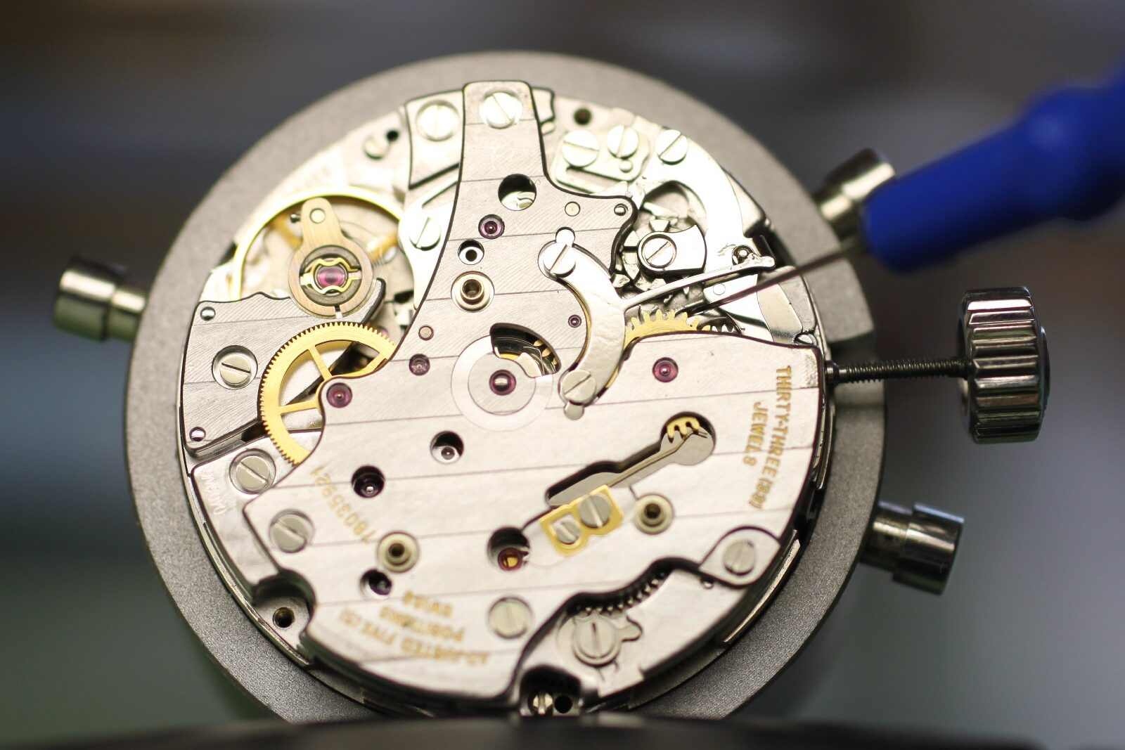
Movement Detail 10
In this calibre, the amplitude should differ hardly at all between a running and a stopped chronograph. The bearing dimensions of the vertical clutch system were designed so that friction is approximately equal in both states. If the amplitude differs substantially, the central chronograph runner is usually defective and must be replaced. Incidentally, the instructions state that this part must NOT go into the cleaning machine. If contaminated, it must also be replaced.
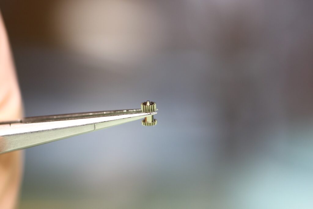
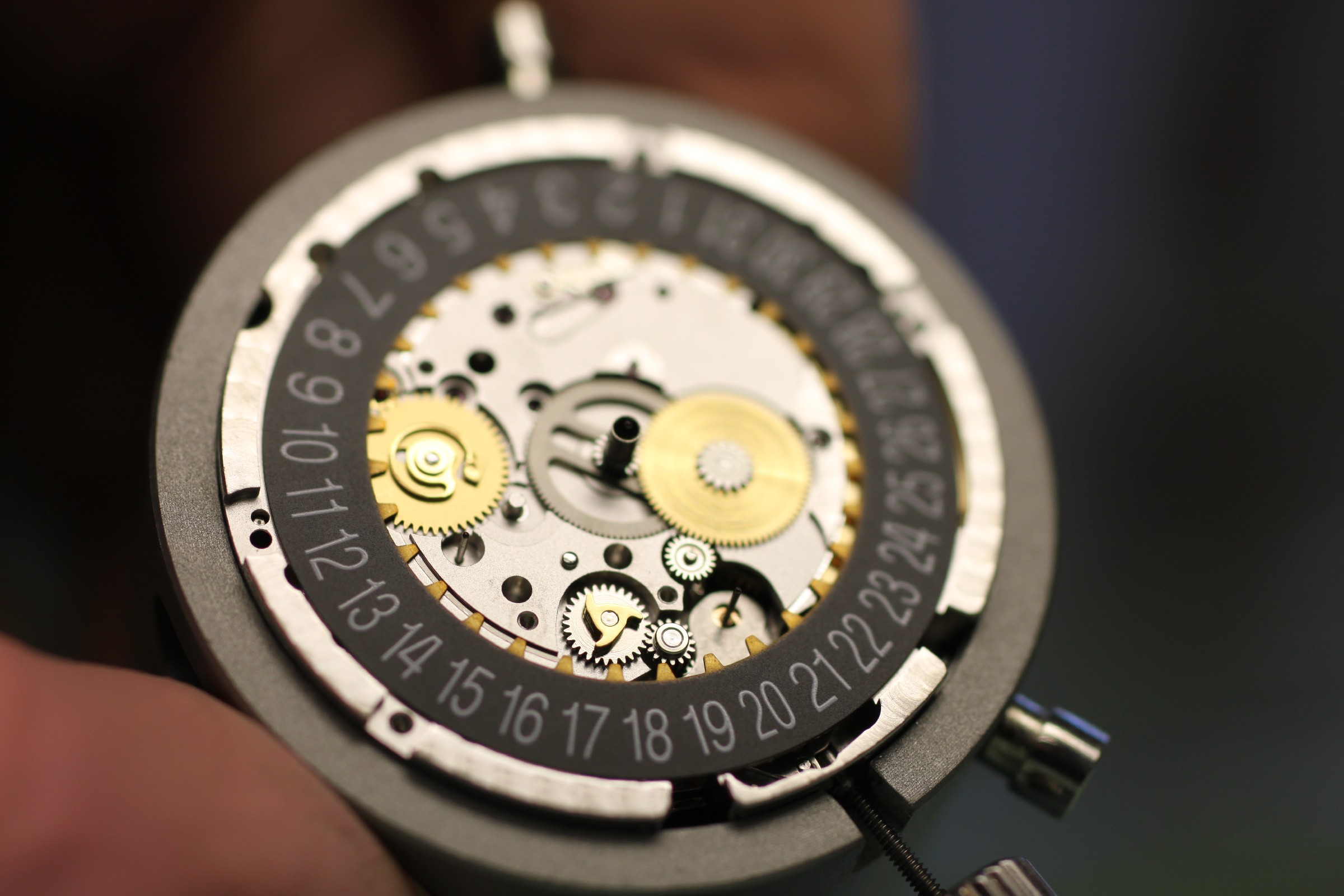
Meanwhile, the date side is disassembled. There are two important points to check here. Adjustment of the quick-set date is covered in more detail during assembly. The pinion in the right-hand photograph is occasionally cracked in its upper half, causing problems when setting the hands.
This would be clearly visible from above.
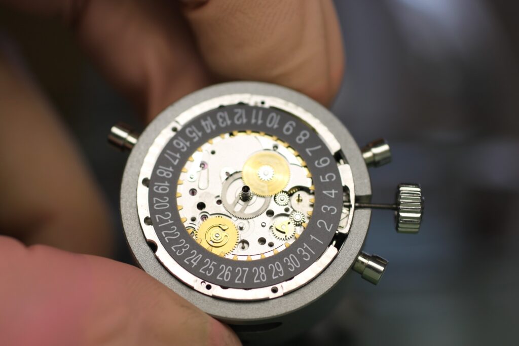
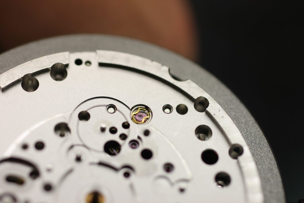
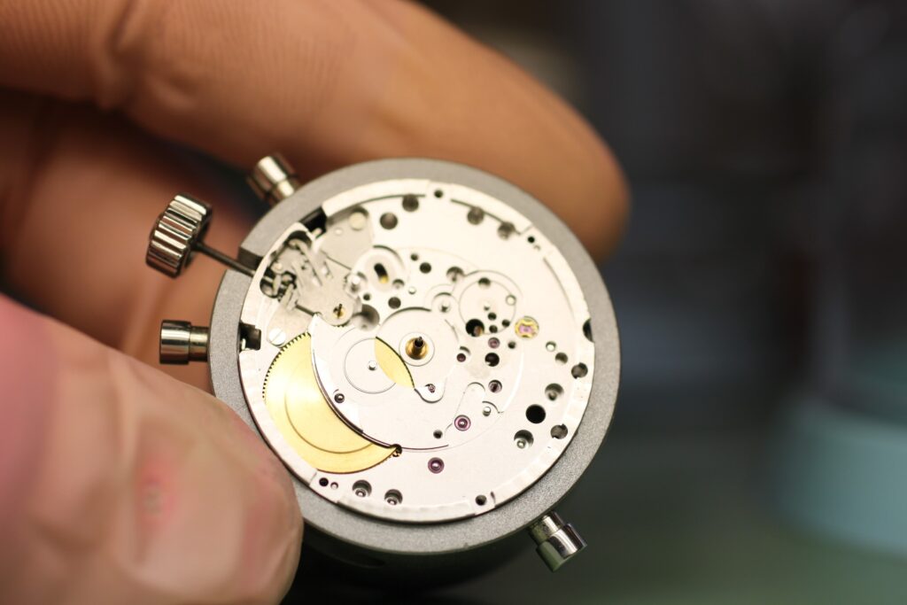
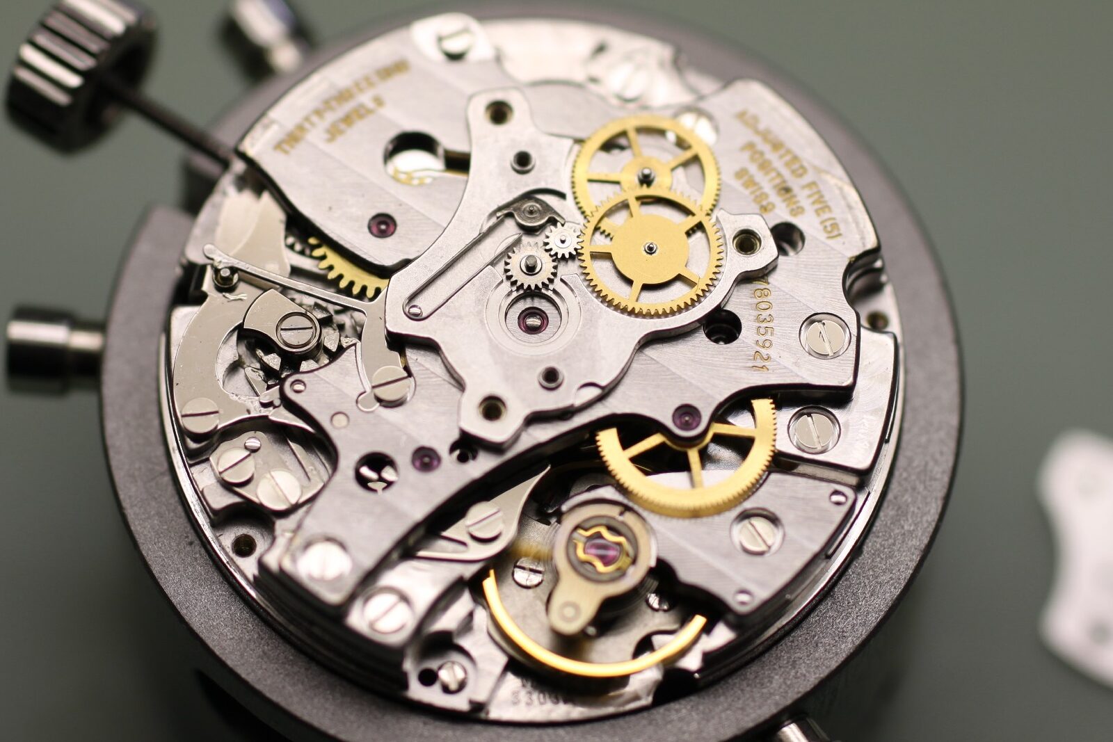
Finally, the movement is shown from the dial side without the date components.
We continue by removing the balance and performing the usual balance and escapement checks.
A look into the gear train shows that the fourth wheel is not in the train’s power path and follows the escape wheel. As bearing friction is its only source of friction, under certain circumstances a very close look may reveal “fluttering” of the small seconds hand.
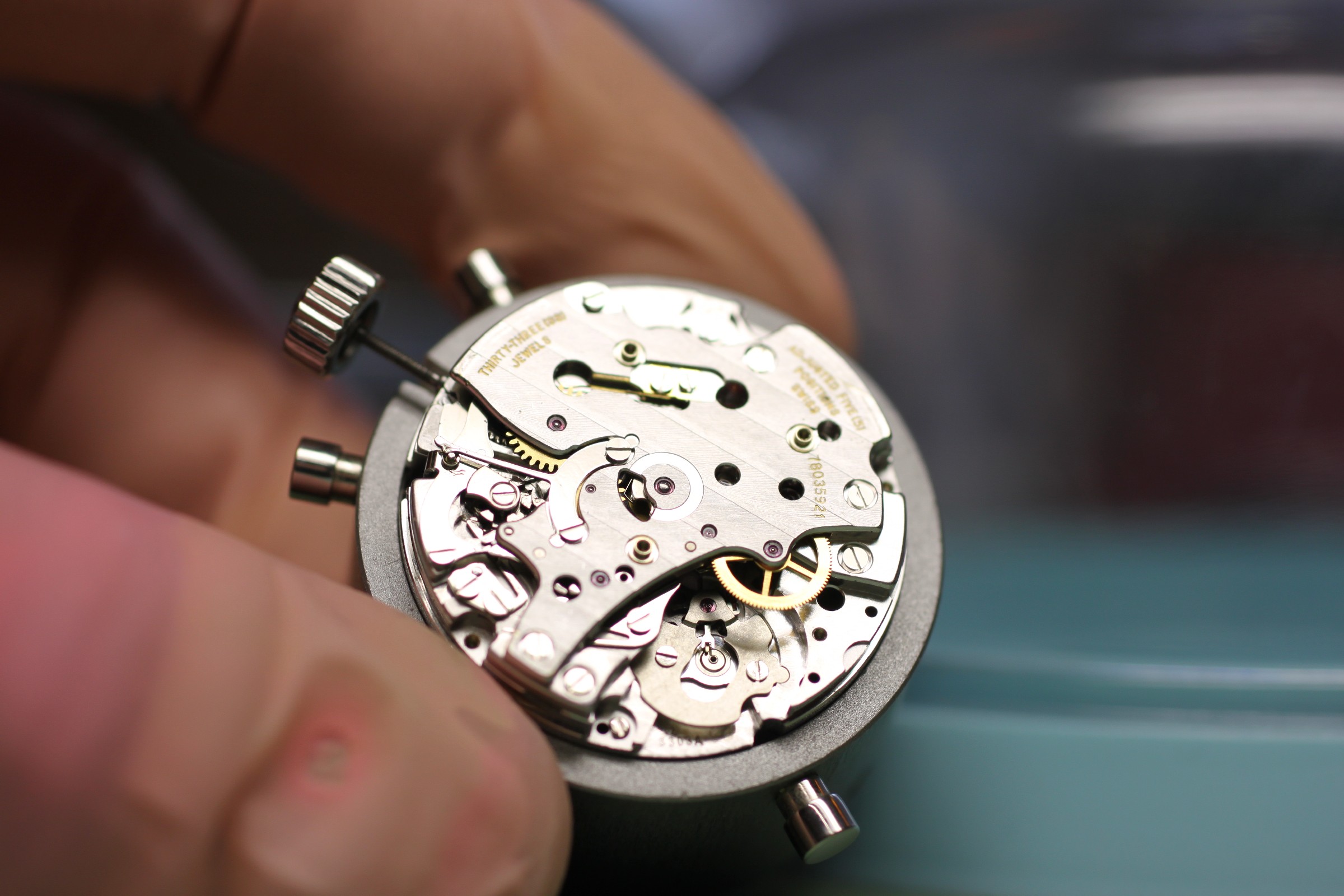
After removing the escape wheel, the wheels can be checked for flat running by turning the crown. Normally, three turns of the crown should also be enough to advance the minute-counter wheel. Otherwise, the minute jumper tension may be too high.
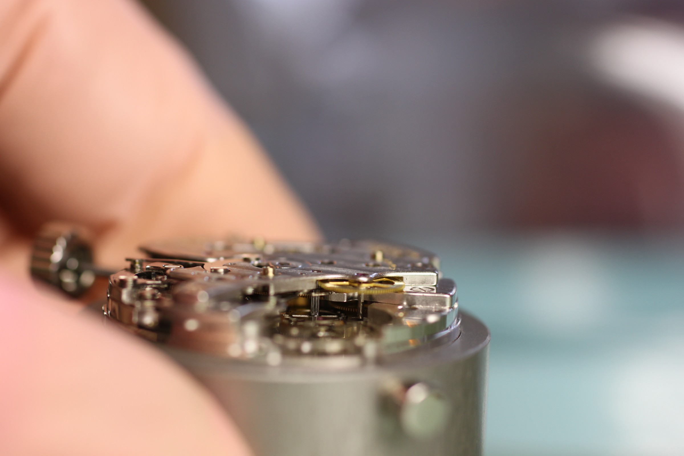
A look beneath the chronograph bridge reveals the hour-counter hammer (the “dolphin”) discussed above.
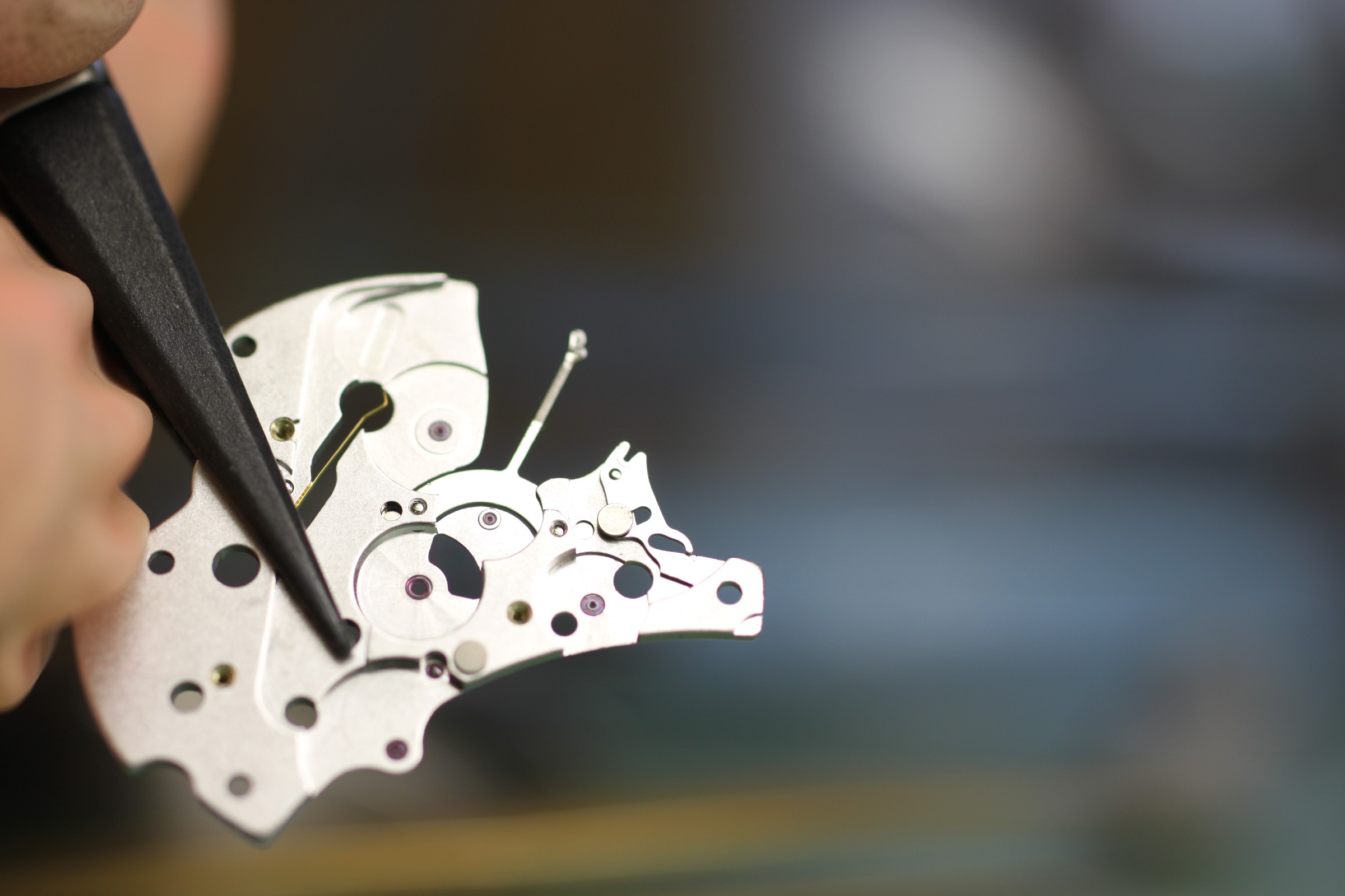
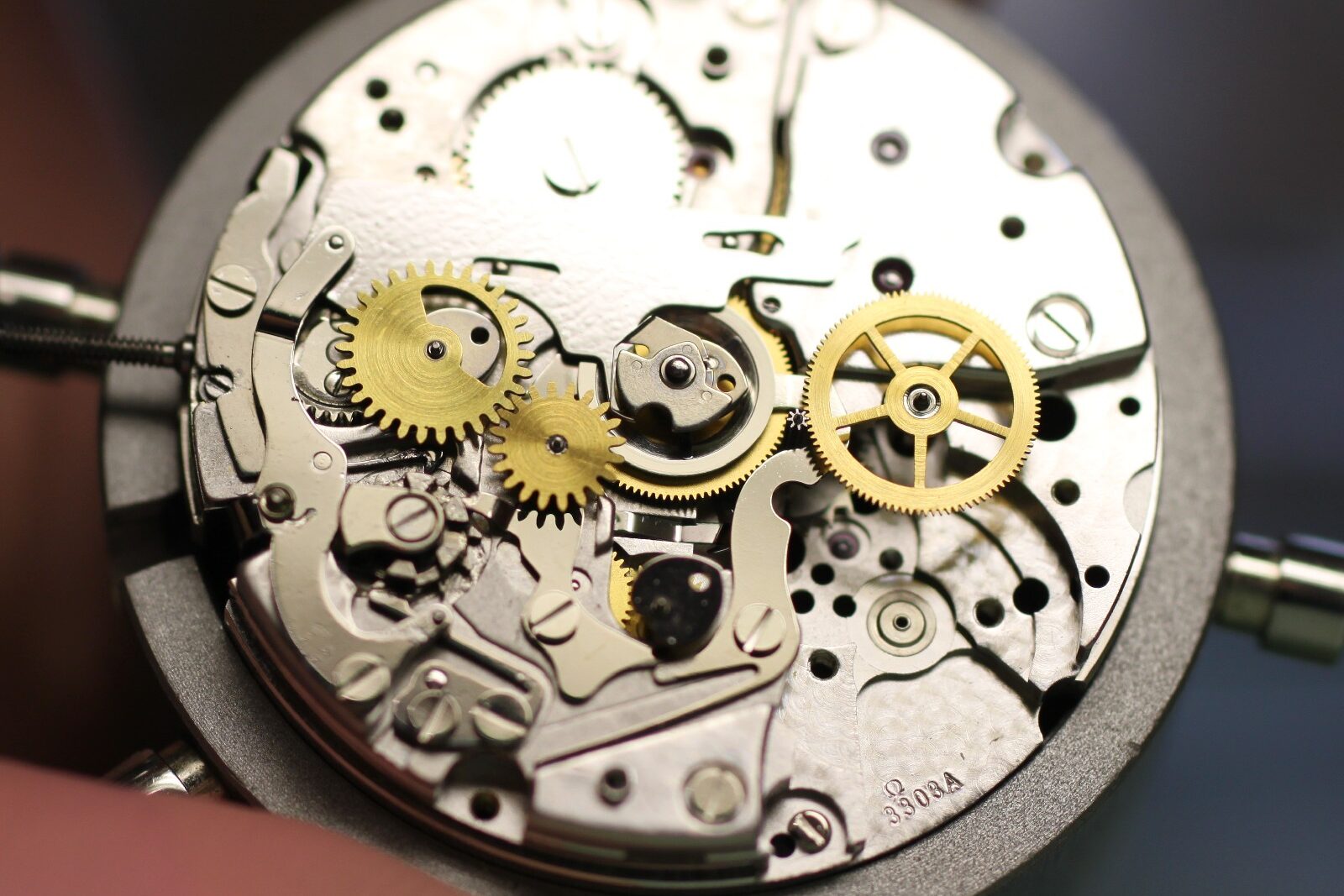
The gear train beneath the bridge.
The two pins guiding the hammer can be pushed in by incorrectly screwing down the chronograph bridge. In rare cases, this leads to uneven resetting of the chronograph.
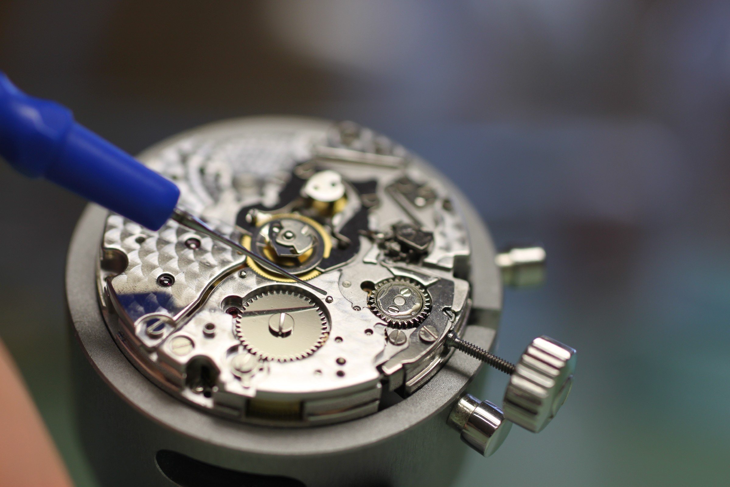
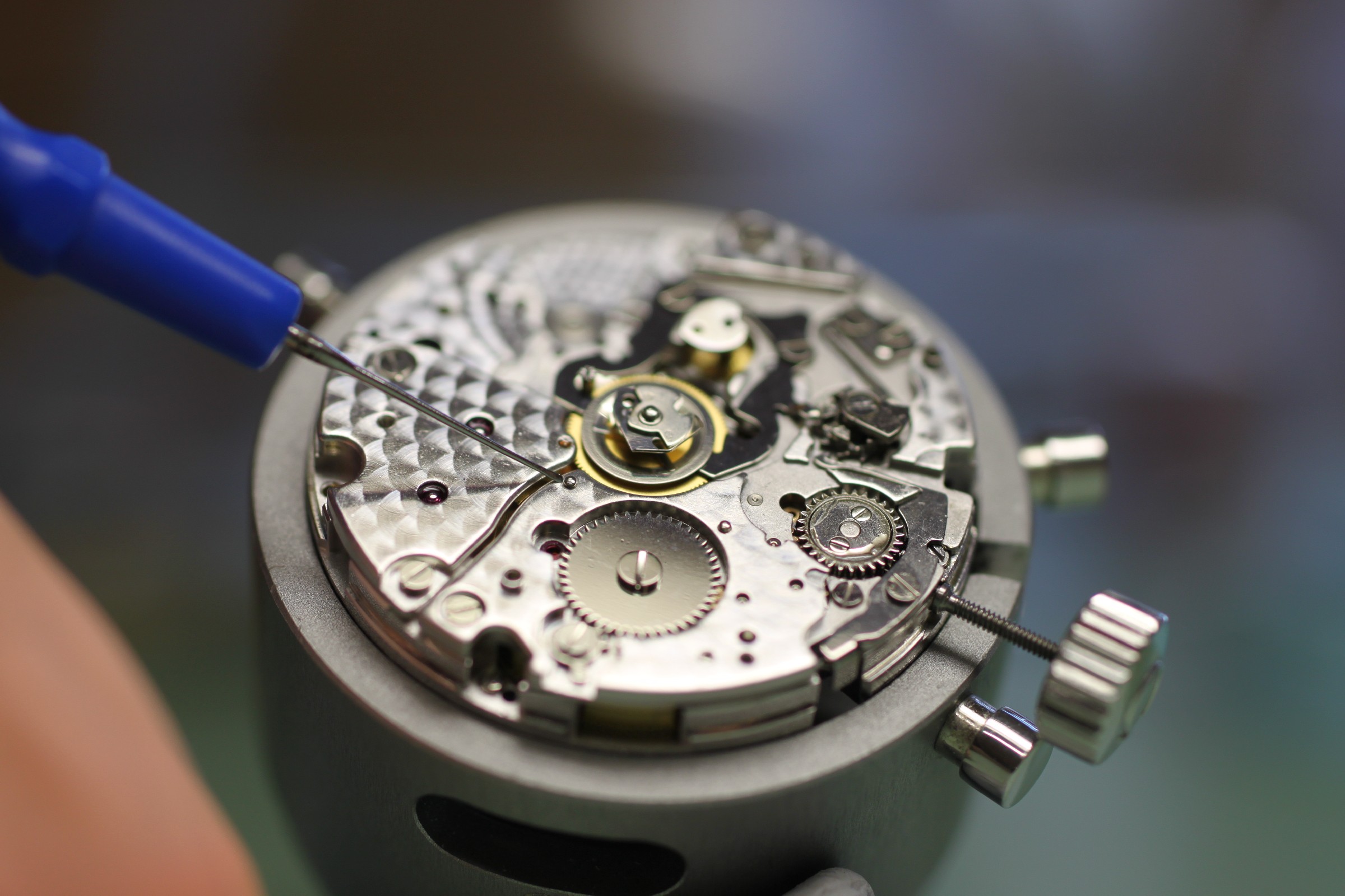
The start/stop lever screw tends to break. This can usually be recognised simply by looking closely. Many screws show two small lines at the bottom of the slot when they are close to breaking: the outline of the thread diameter can be seen “through” the head.
Damage is even more apparent when the two halves of the head reflect the light differently.
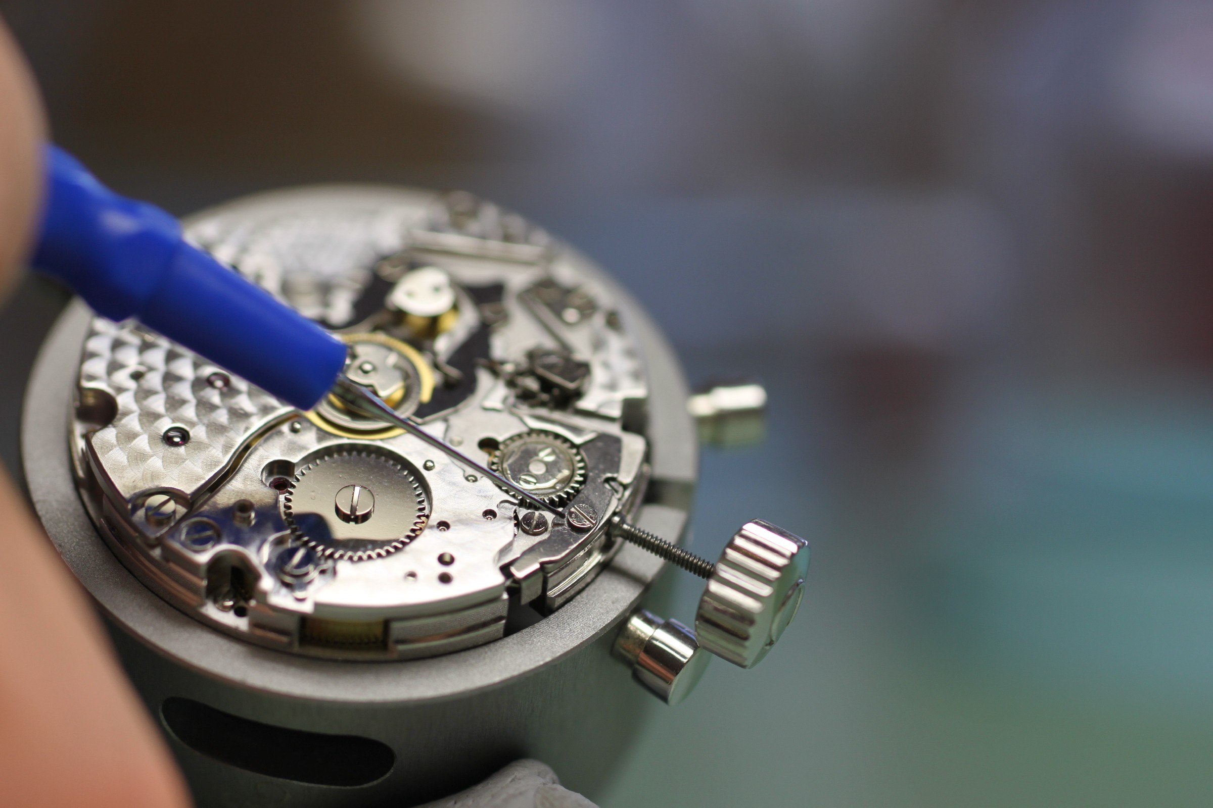
In this view, the clamp in the centre holds the core of the chronograph runner. The chronograph is stopped because the part of the central chronograph runner firmly attached to the arbor is held. It is lifted “upwards”, and the golden wheel can rotate freely on the arbor – so the watch runs without the central chronograph hand.
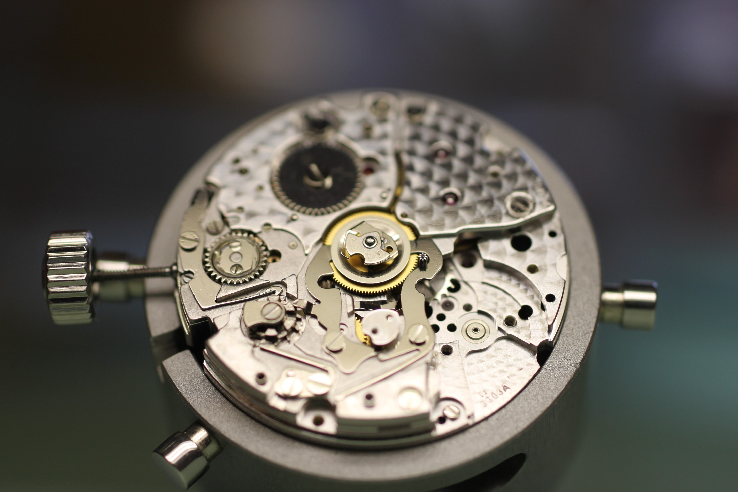
When the start/stop lever is operated, the clamp releases the central chronograph runner. The spring-loaded metal ring is pressed downwards, firmly connecting the golden wheel to the arbor carrying the central chronograph hand. The movement now drives both itself and the chronograph.
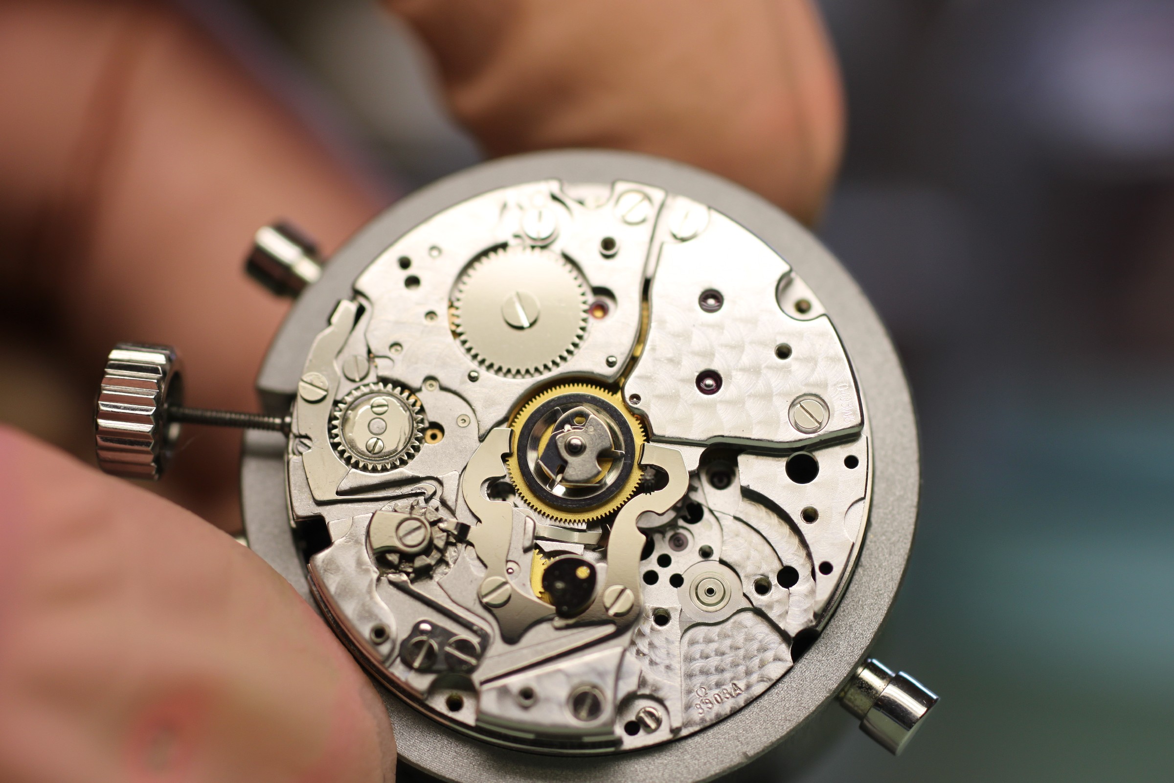
The next sequence of photographs shows operation of the start/stop lever. There is a fault: as the lever returns, its arm can rise above the column-wheel teeth instead of remaining at the same height and sliding backwards over them. If this fault occurs, the endshake of the bush on which the start/stop lever moves must be reduced.
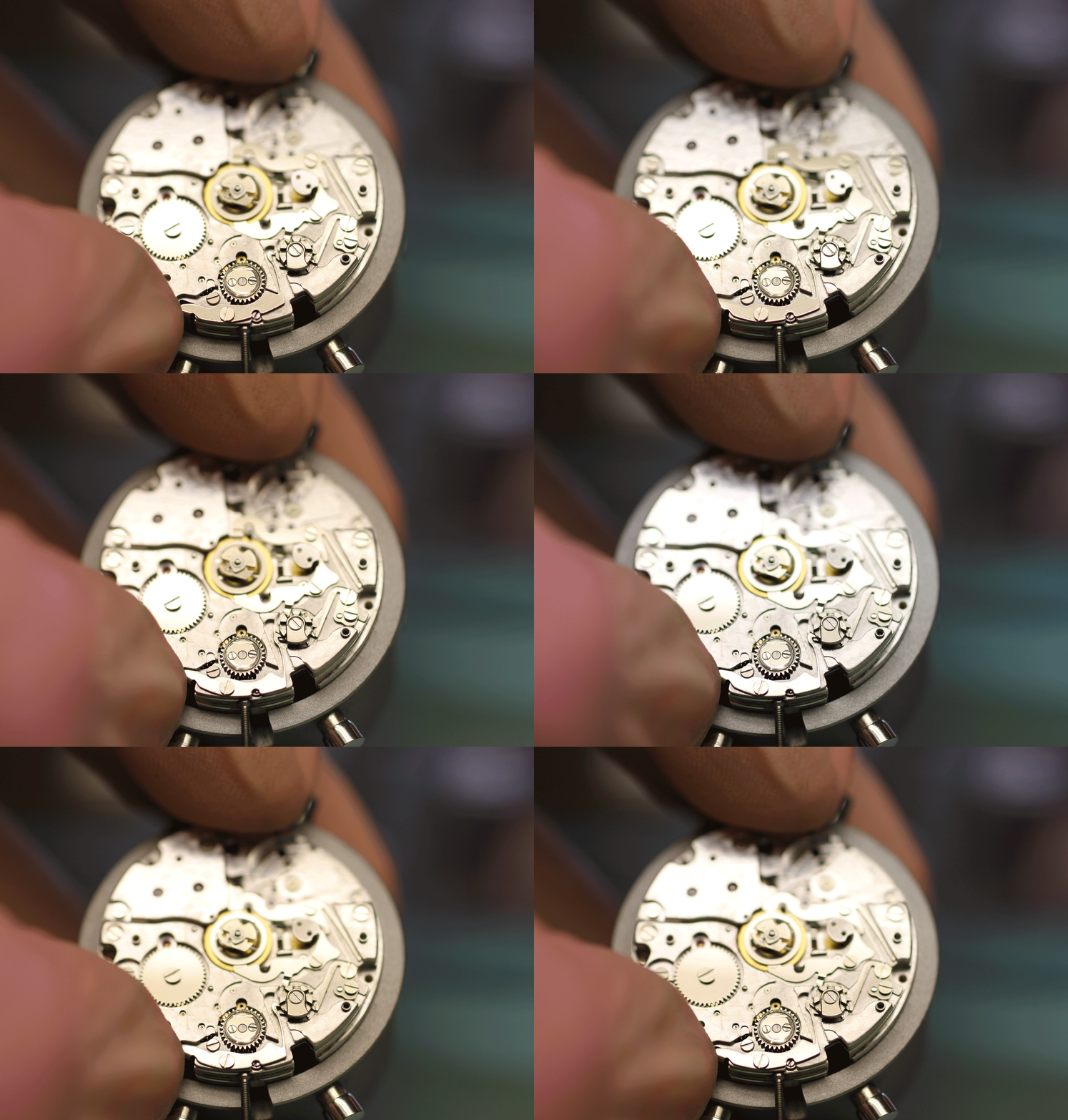
Operation (still with excessive lever endshake – , visible on the return stroke of the operating arm):
Excessive lever endshake can be corrected with the jewelling press or staking tool, through the screw or directly on the bush.
The column-wheel bearing bush visible on the right must be examined carefully. A strong impact on the reset pusher while the chronograph is running can bend or break it.
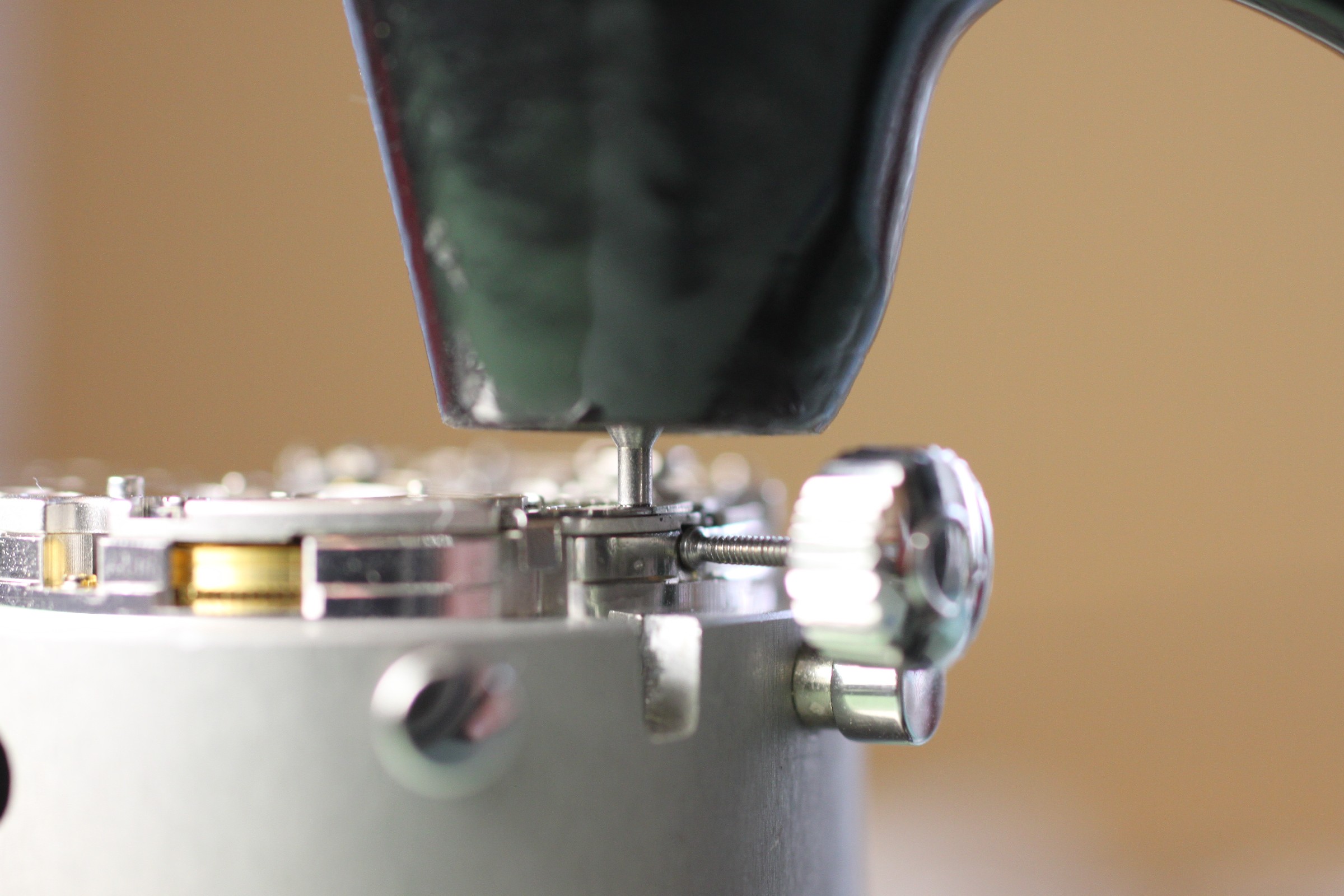
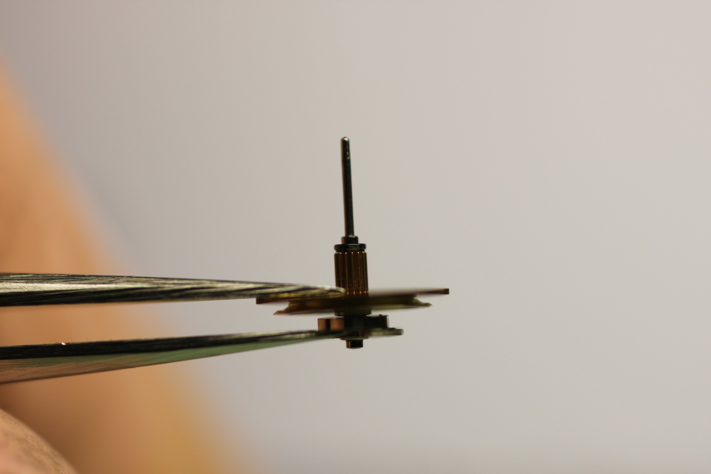
The central chronograph runner can continue to be used if it passes the amplitude test and its advancing finger can be brought into the correct position. All teeth must also be intact, and light contamination must have been removed with pegwood and other aids.
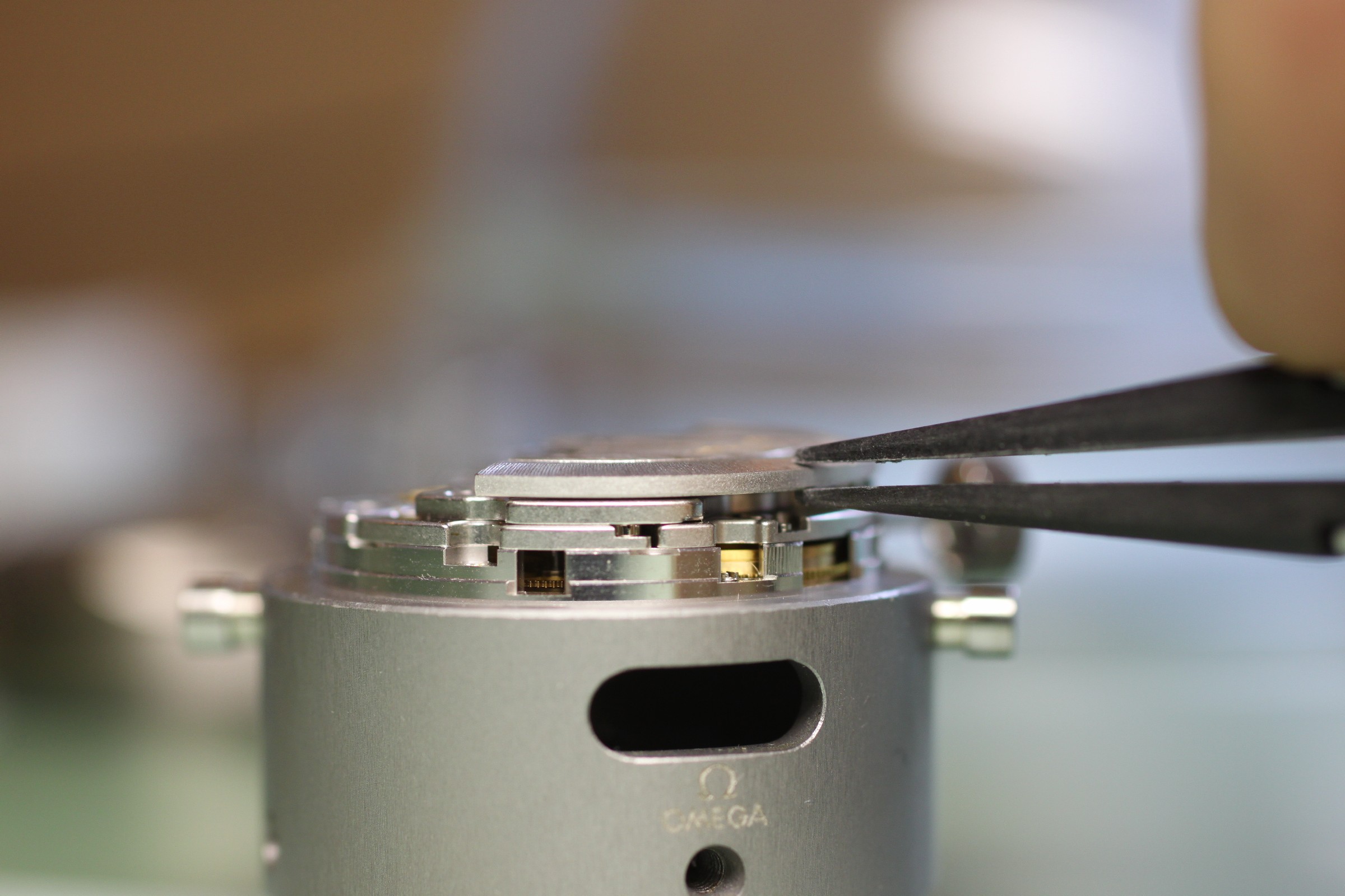
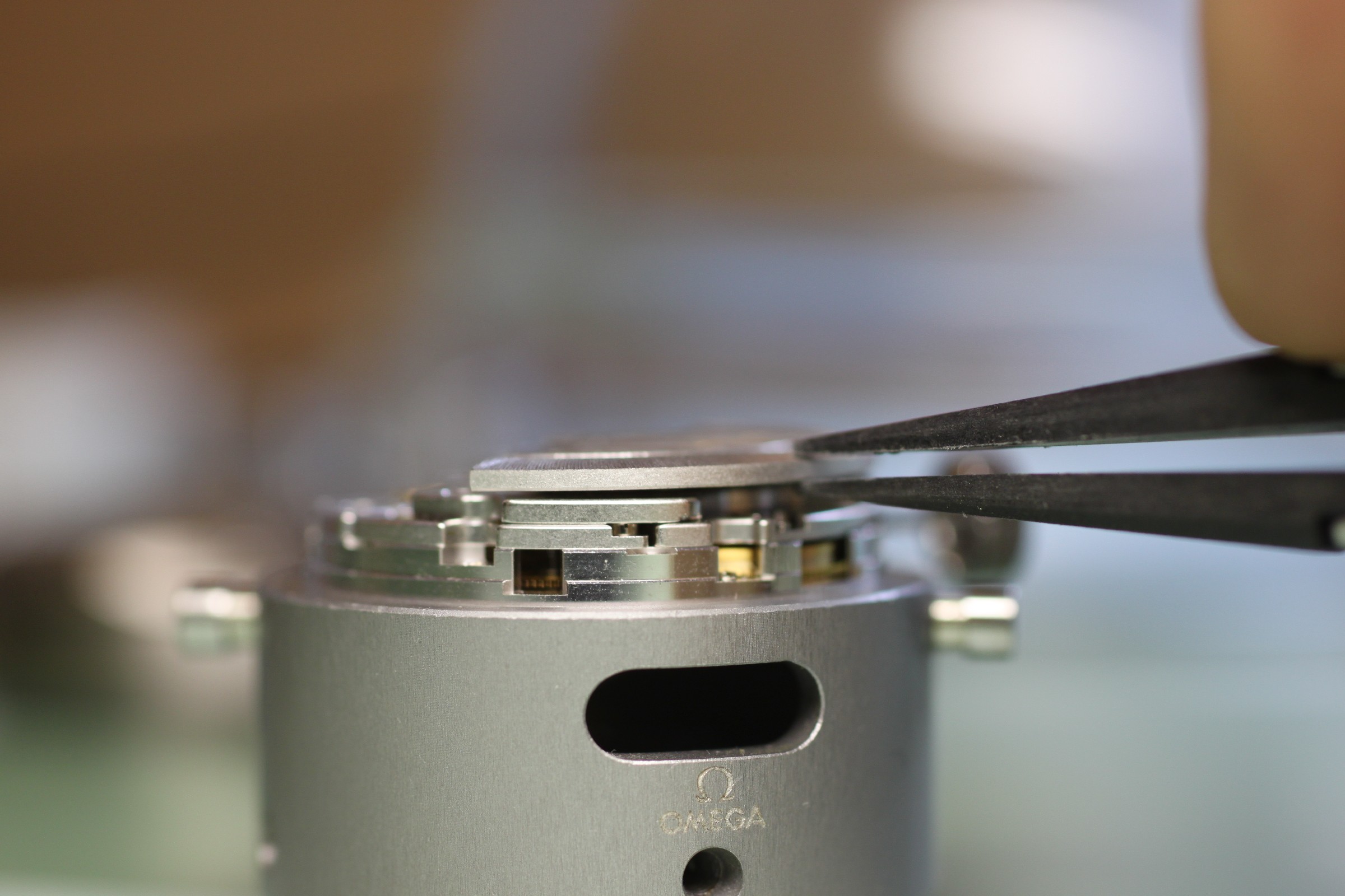
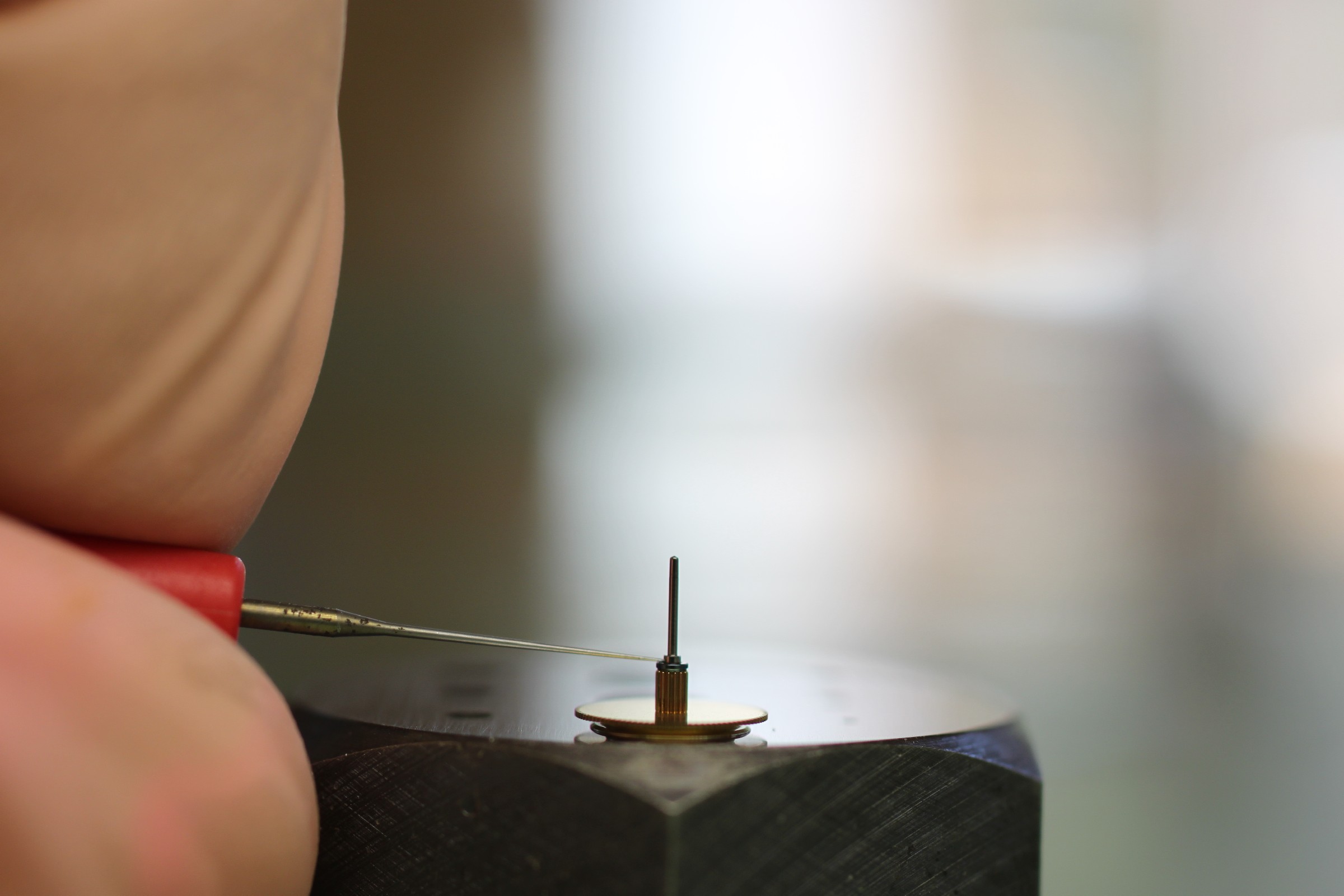
It is also very important that the internal endshake (checked by pressing the tweezers as shown in photographs 1 and 2) is not excessive, and that a small quantity of oil is visible in the gap between the blue ring and brass pinion. This oil is difficult to see and is best checked under the microscope while alternately moving the brass pinion back and forth by pressing and releasing the tweezers.
The endshake can be reduced by sliding the blue bush a little downwards towards the arbor.
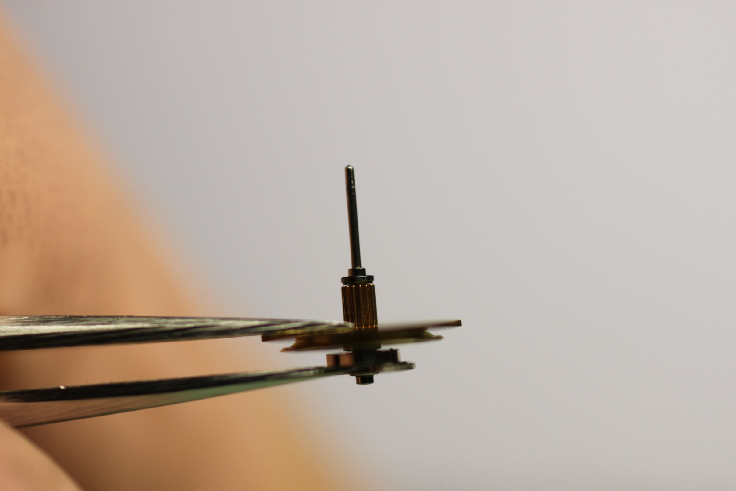
The wheel must not go into the cleaning machine, but must be replaced if more heavily contaminated.
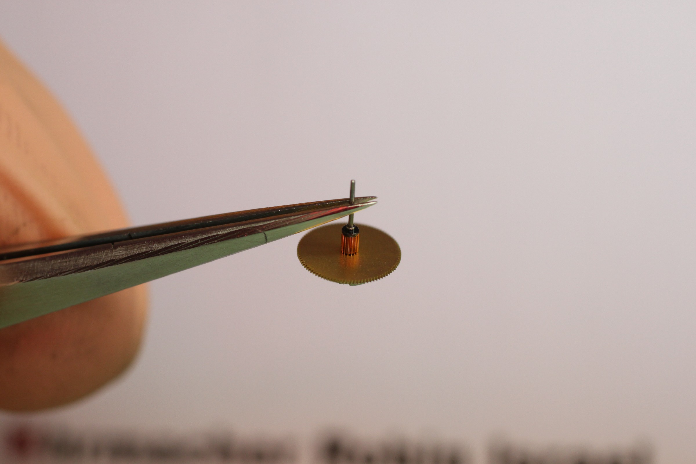
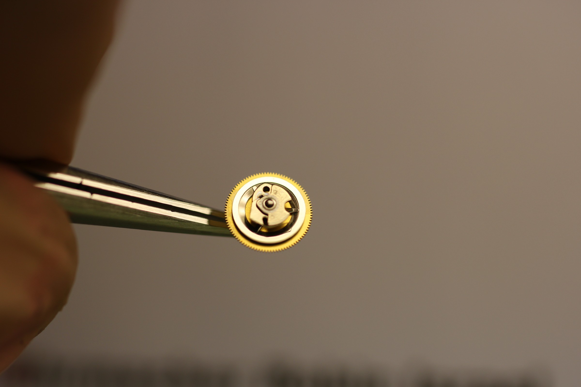
The bearing must be lubricated at the point indicated by the oiler. Occasionally, central chronograph runners are found lubricated between the long pivot and the first shoulder, but not at the actual bearing point – : very poor conditions for good timekeeping with the chronograph running if a bearing remains unlubricated.
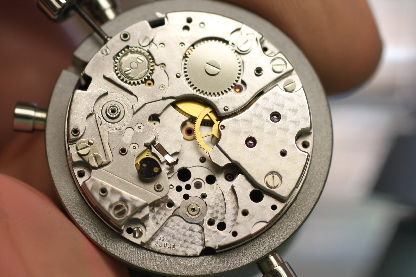
The next photograph shows the remaining gear train and the barrel bridge, with crown wheel, ratchet wheel and hour-counter mechanism. The crown and ratchet wheels are connected by three small wheels beneath the barrel bridge. These are particularly delicate and are a weak point.
The crown wheel, core and its two screws are shown on the staking anvil. To the right is a date-bridge screw. Accidentally fitting one of the longer screws can prevent the crown from being pulled out through interference with the stop-seconds lever:
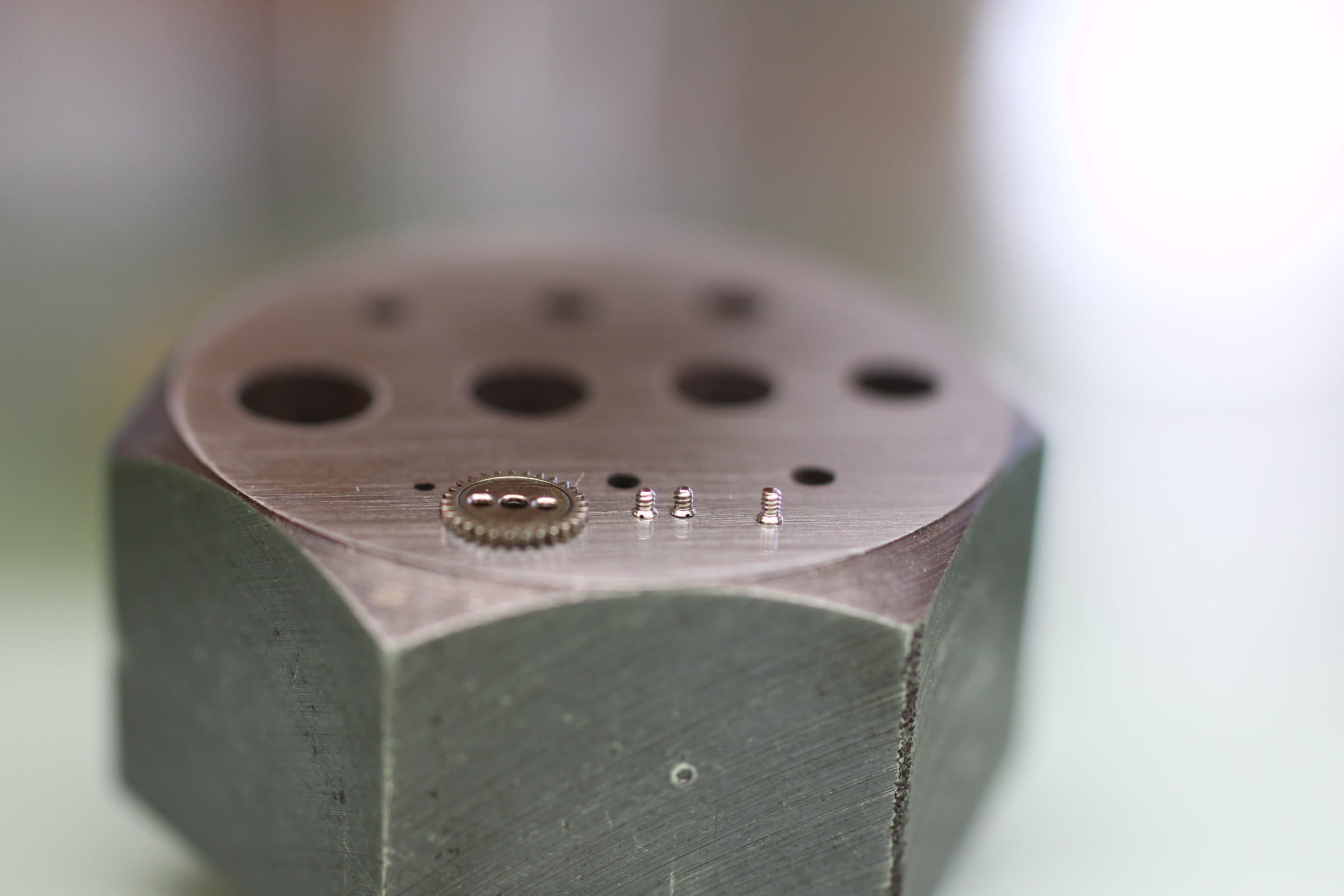
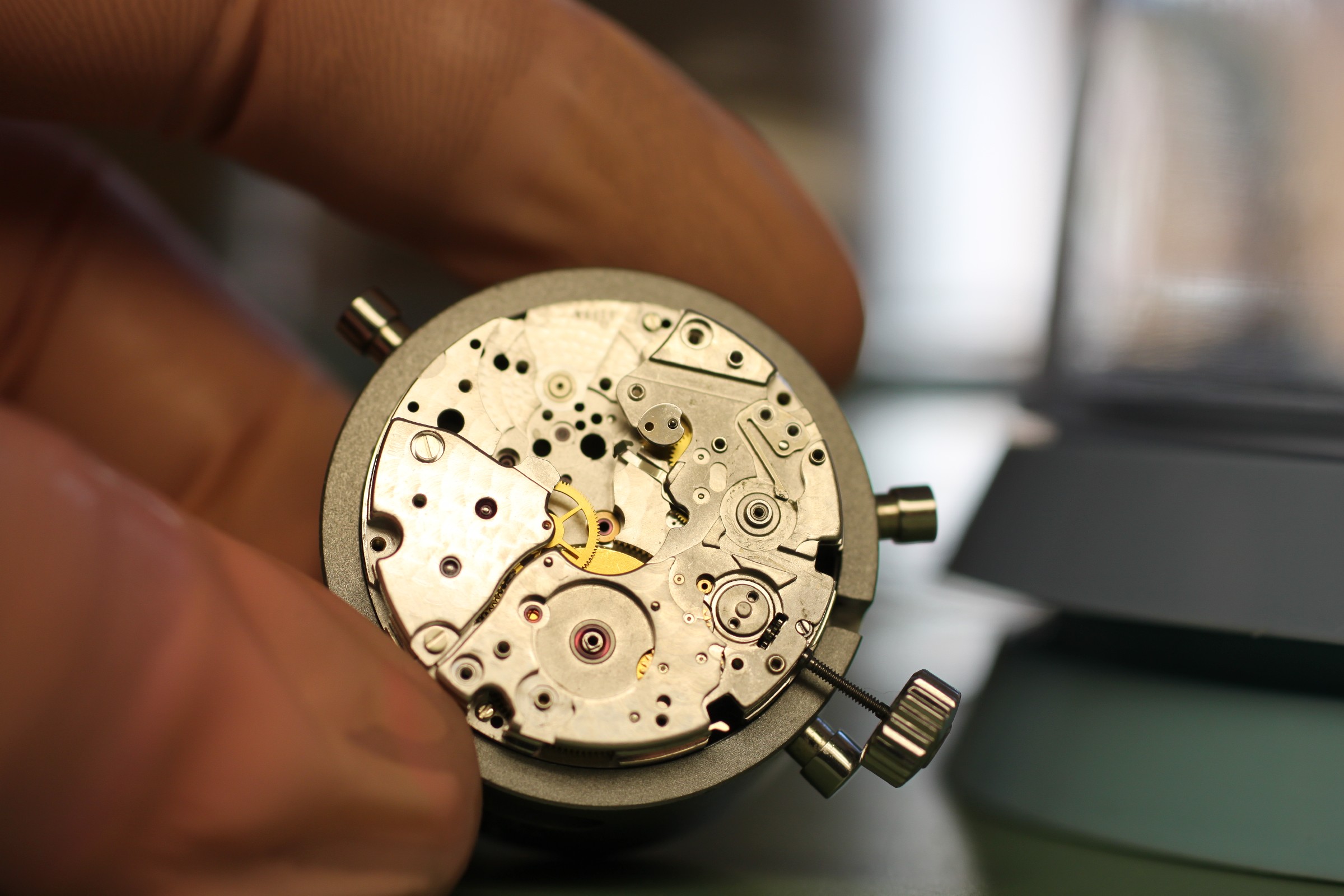
Some components removed so far show that particular care is needed to use the correct screws.
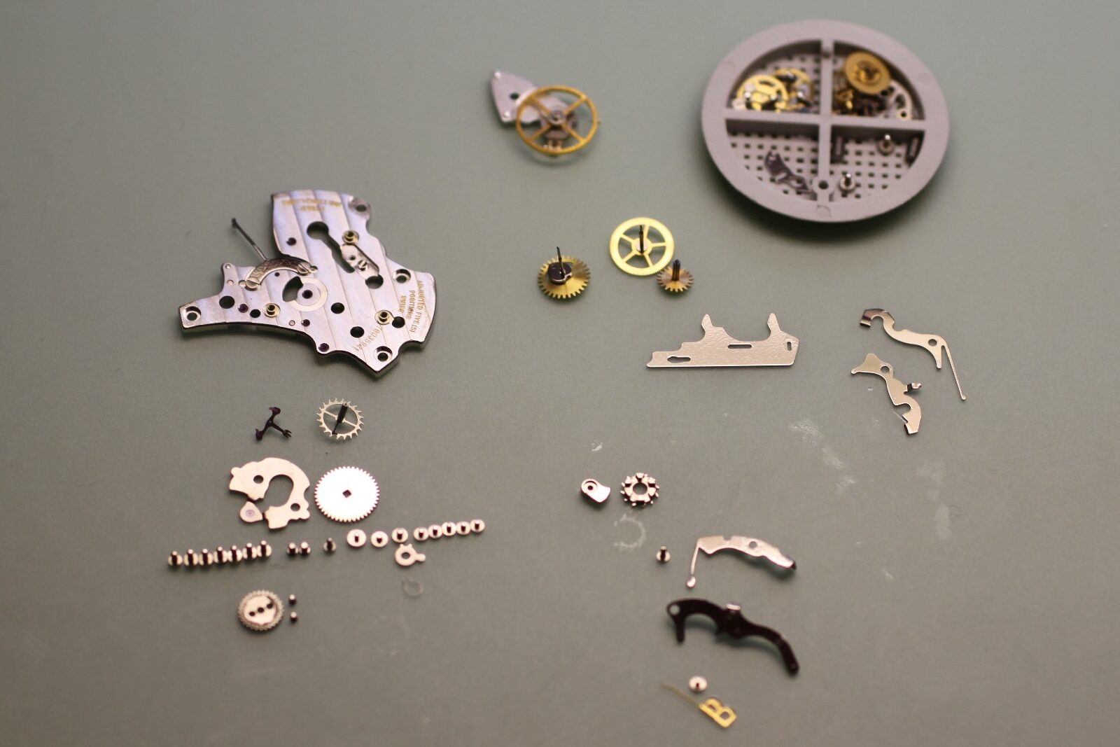
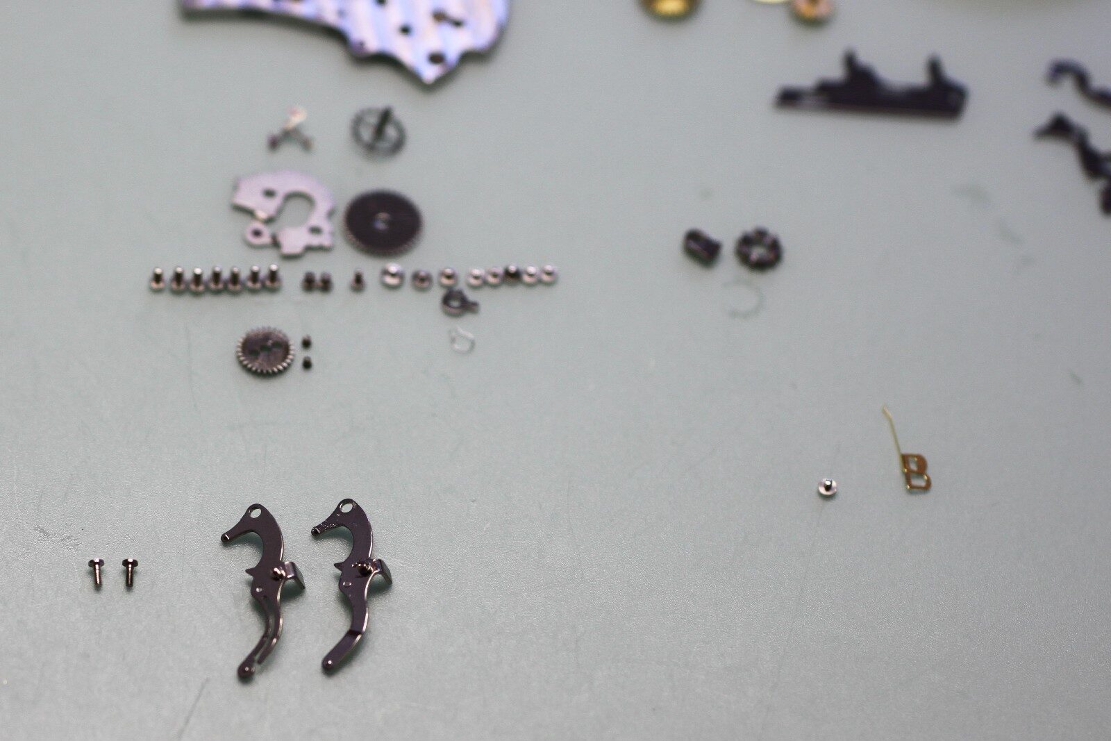
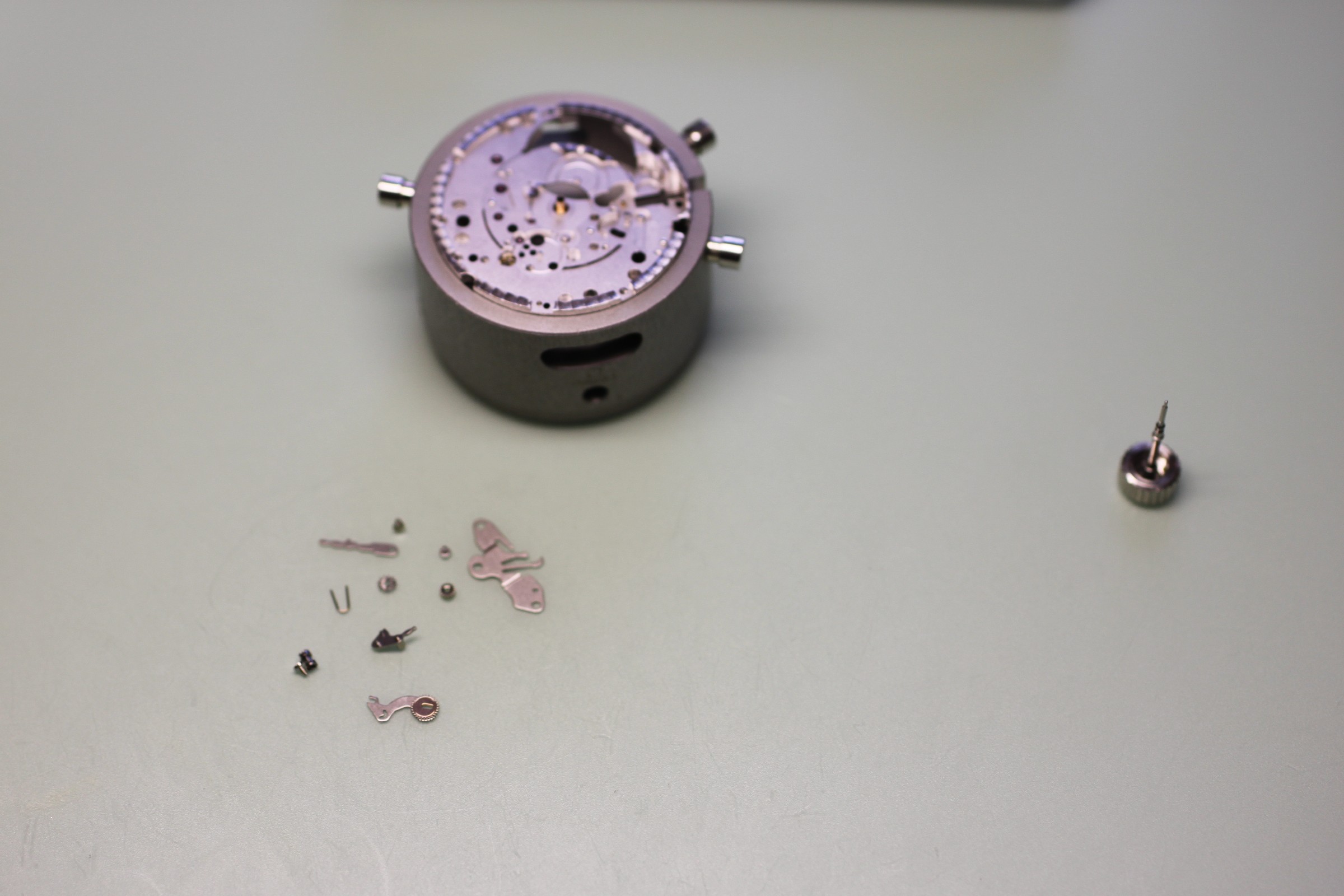
Some parts were redesigned for improved shock and impact resistance. Omega’s instructions require them to be replaced during servicing. The centre of the photograph shows the new column-wheel screw and reset lever (each on the left). Other replacement parts for this calibre include the start/stop lever and minute-counter jumper, which in this case are already current.
Disassembly continues.
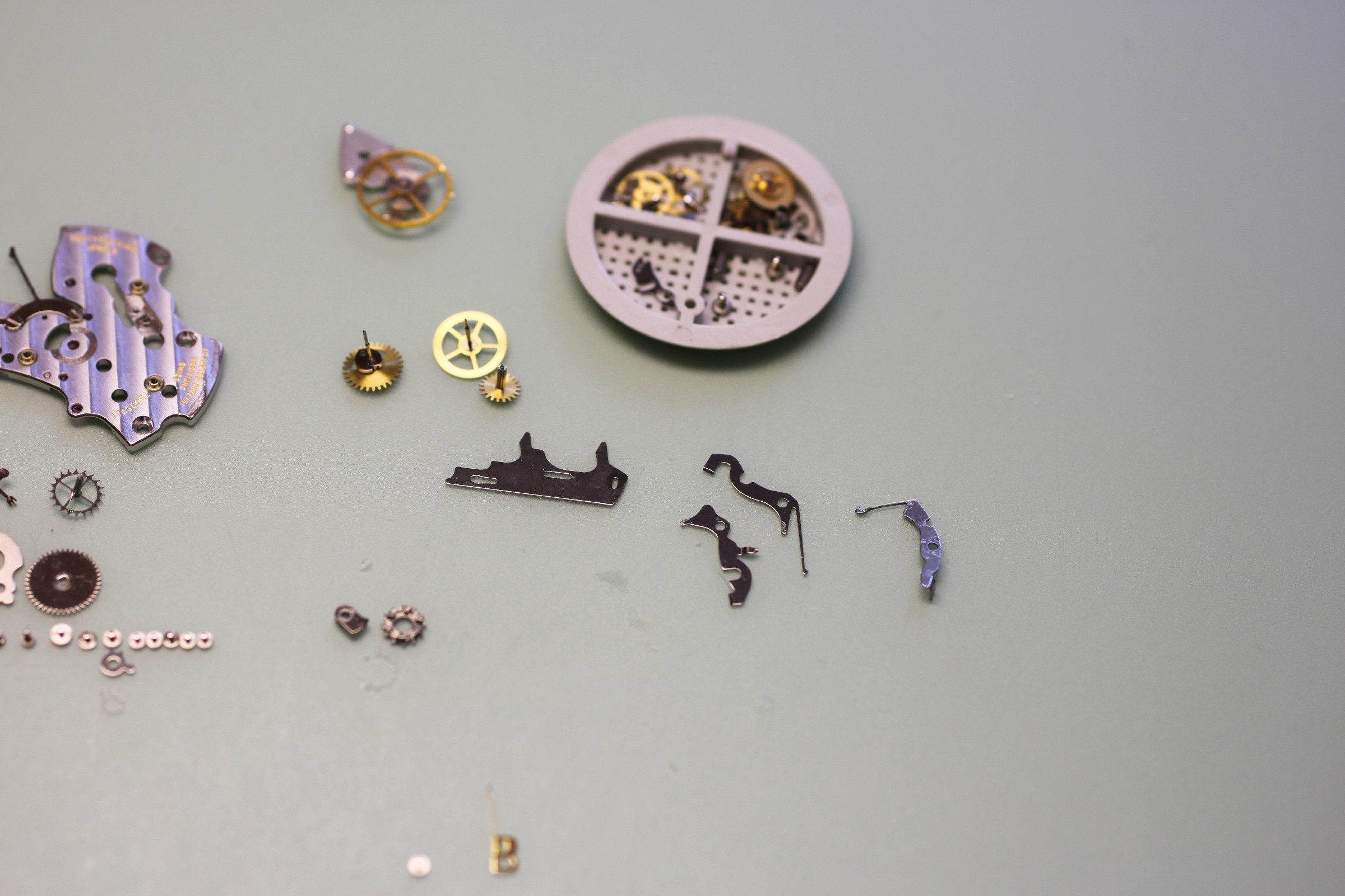
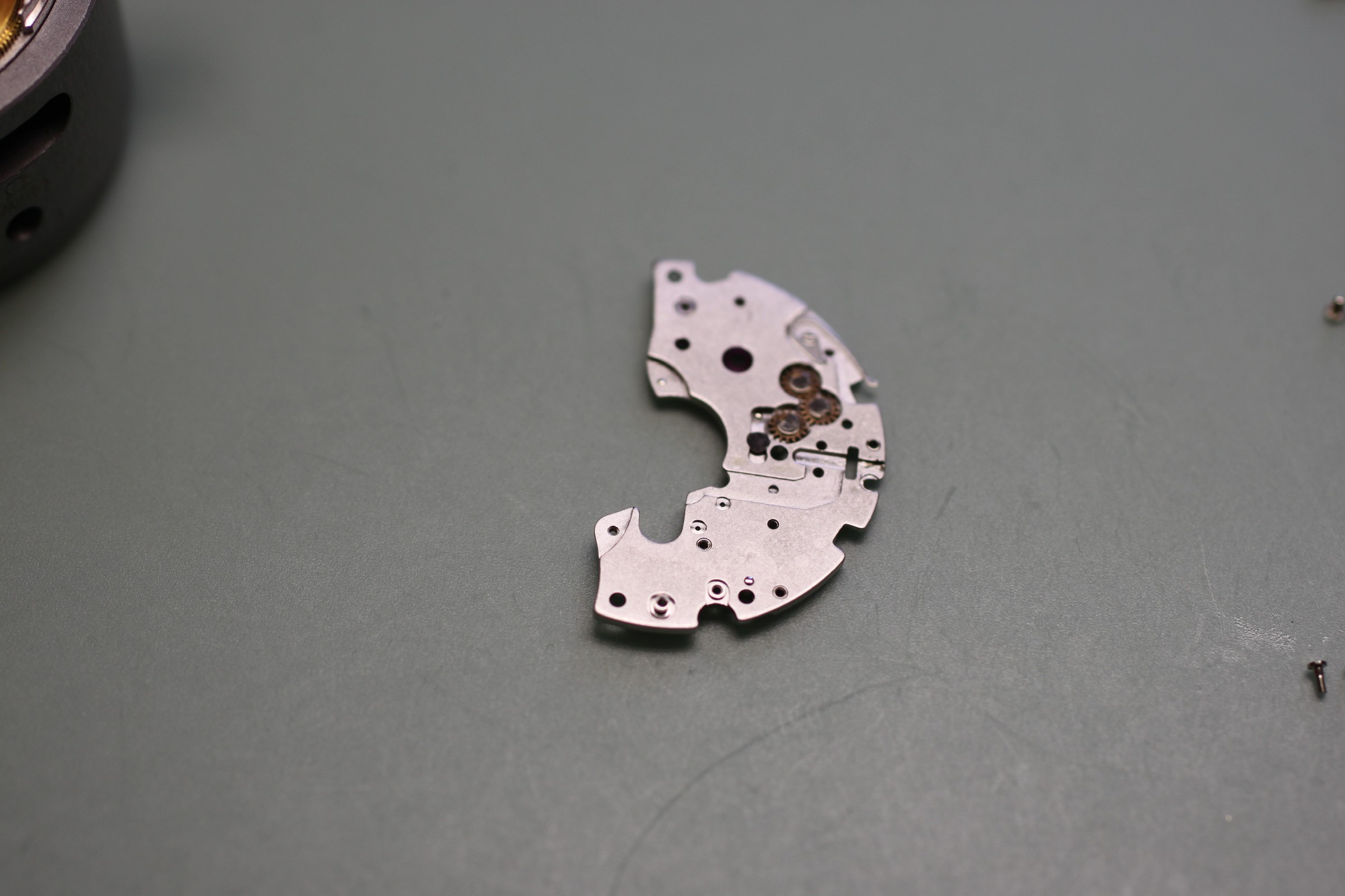
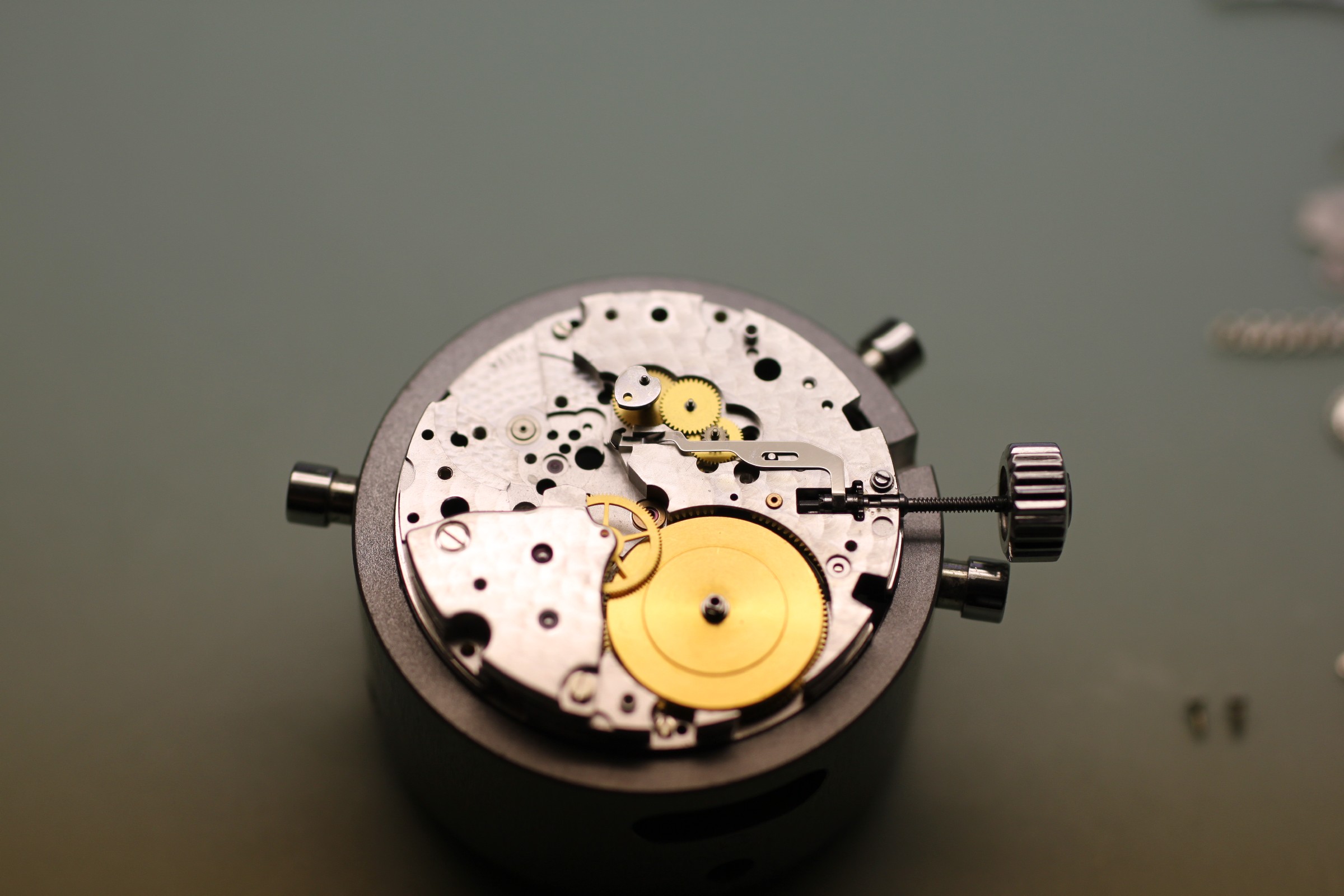
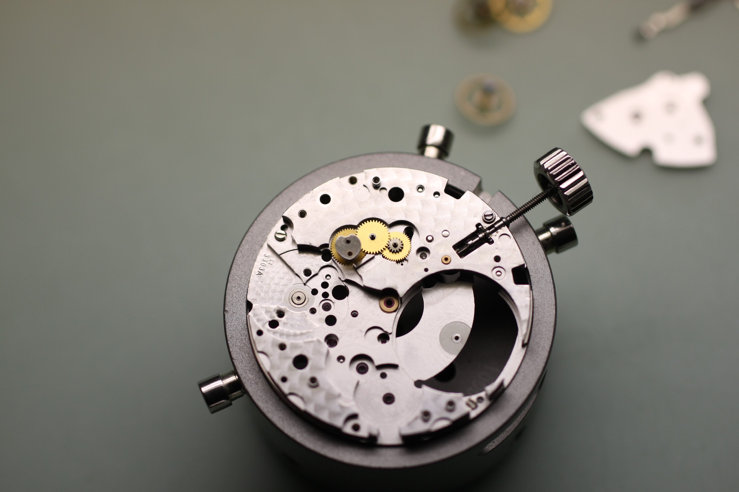
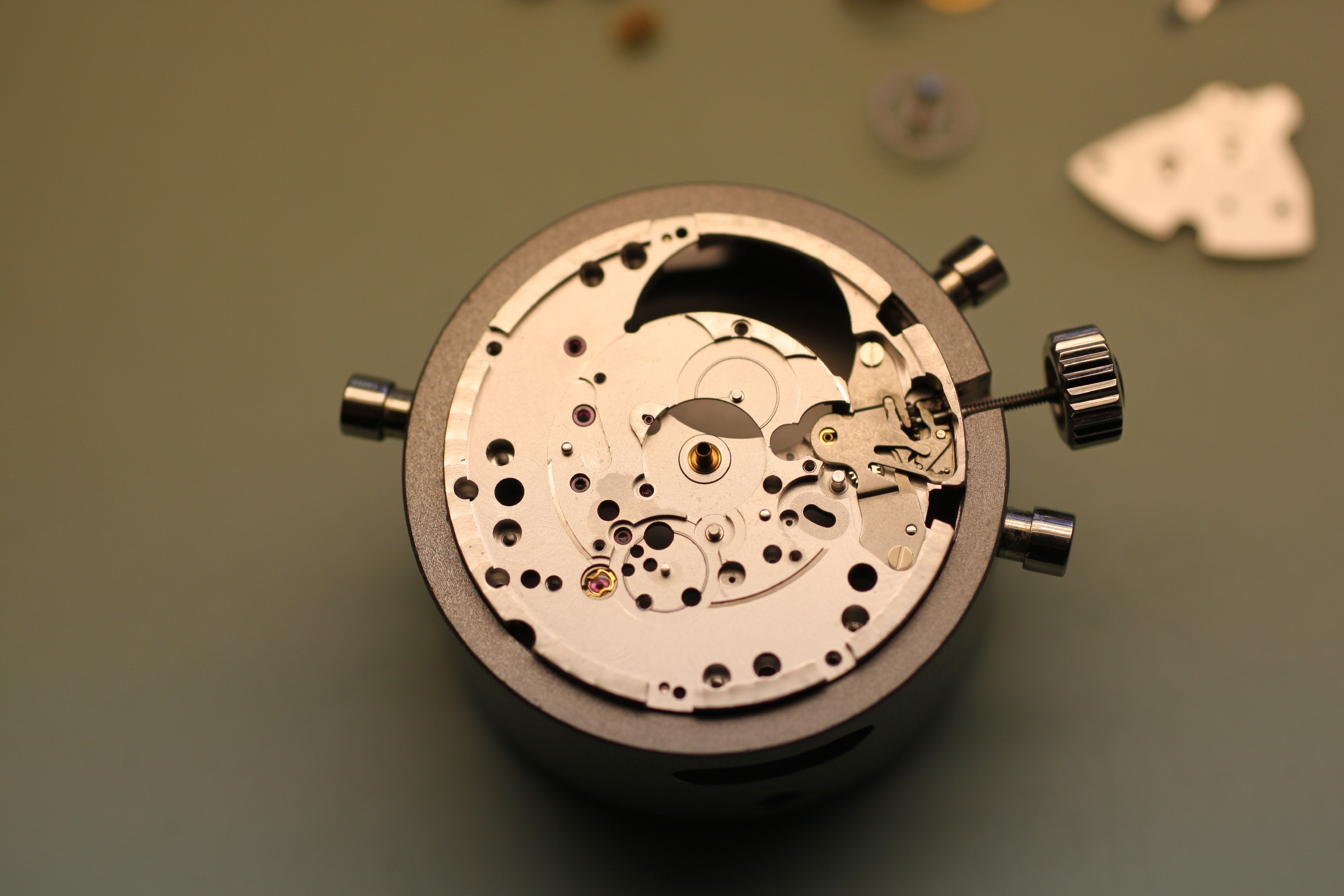
The final components to be removed: the winding and hand-setting assembly:
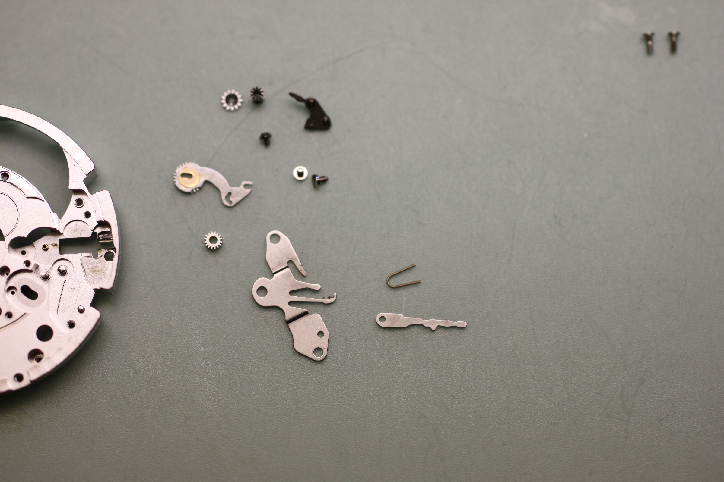
The nose of the setting lever (photograph below) tends to bend after strong impacts on the crown. Frequently, this prevents selection of the winding position, leaving only the date and hand-setting positions functional. Since the setting lever is among the last parts handled during a complete service, this fault often entails a complete repair even though only one small part is actually damaged.
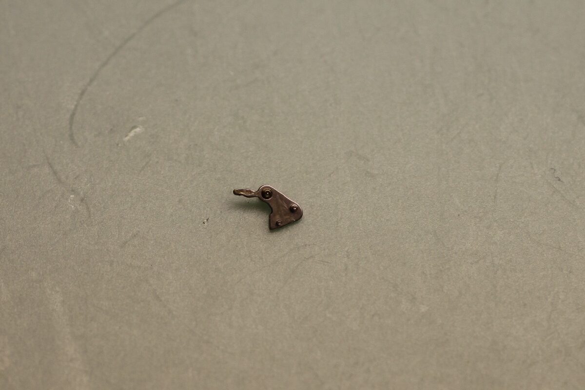
The transmission wheel and crown wheel must always be replaced as a pair. Here too, a stronger version was developed because minor faults in the automatic system or the small wheels beneath the barrel bridge cause high loads on these wheels during manual winding:
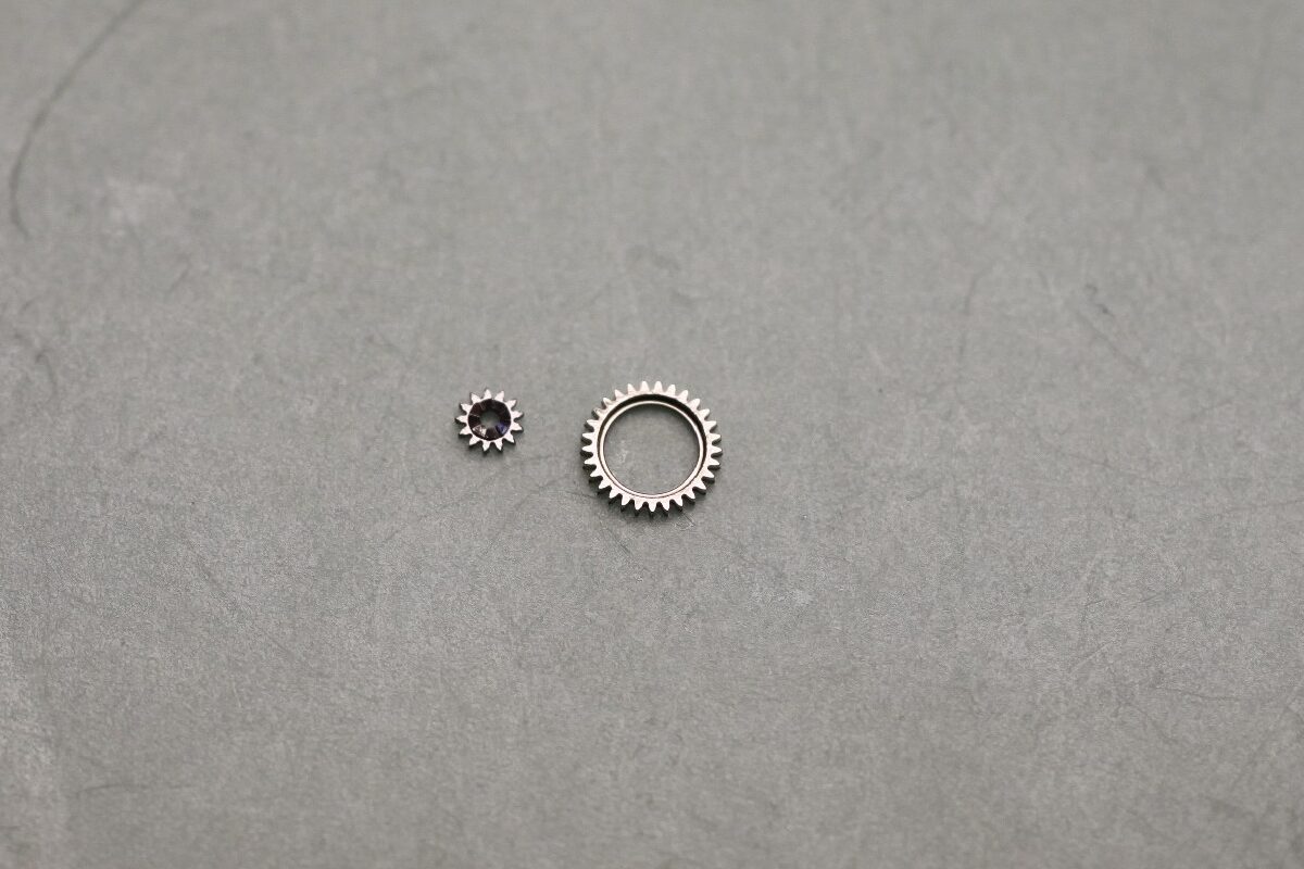
If the setting lever has been bent, this lever must also be replaced with the new version shown below:
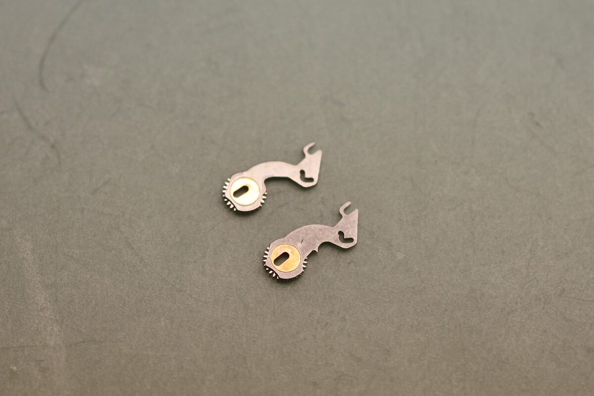
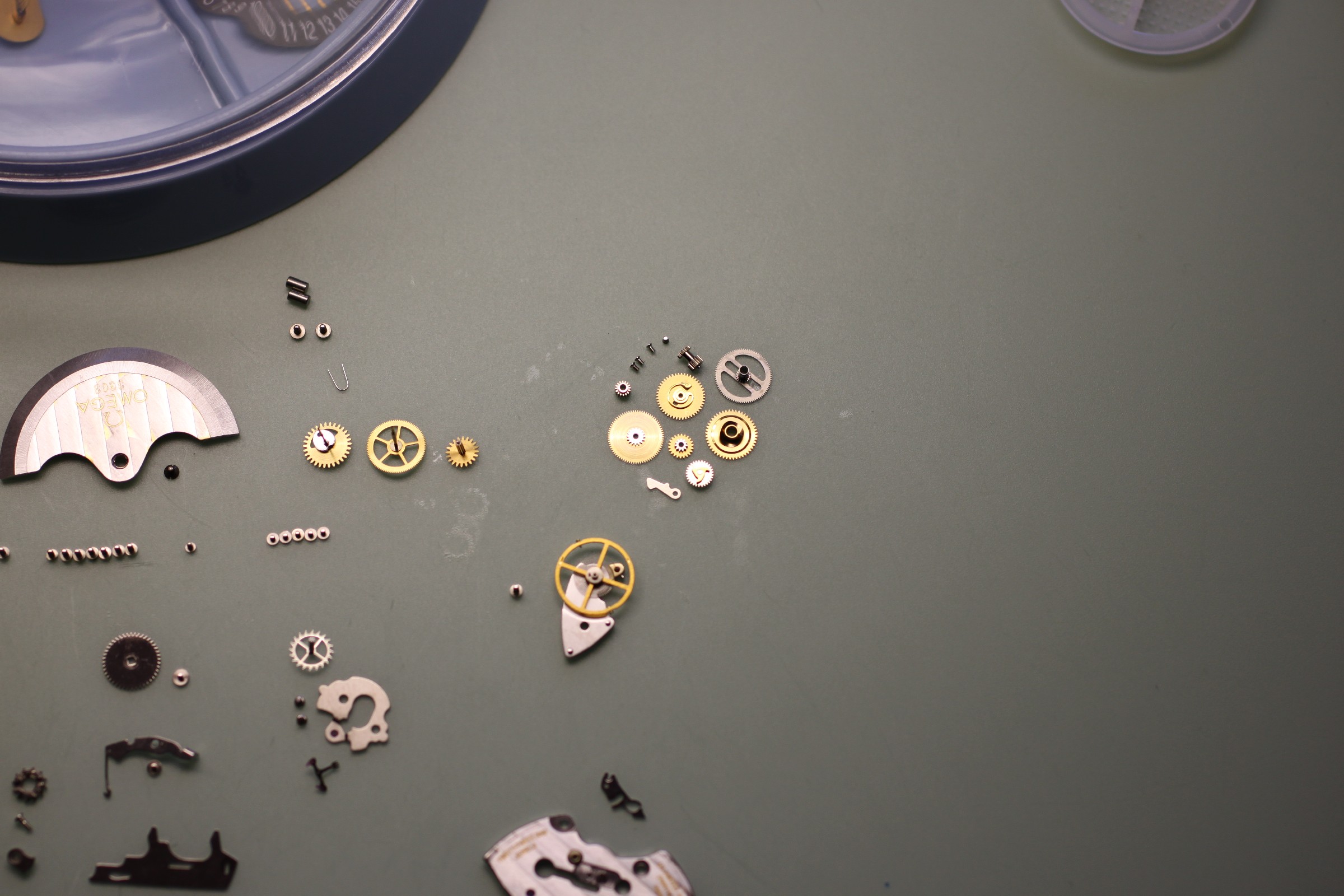
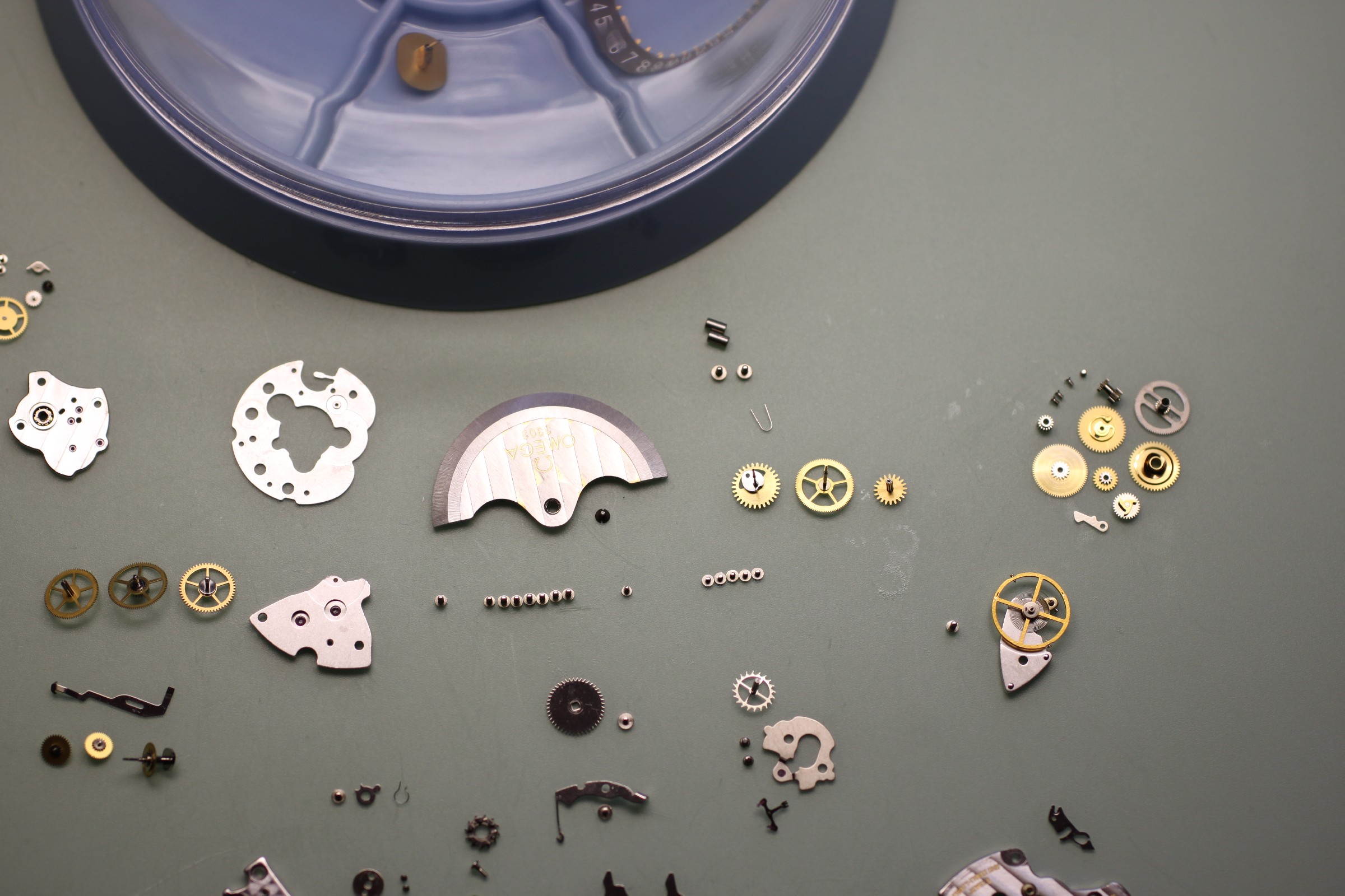
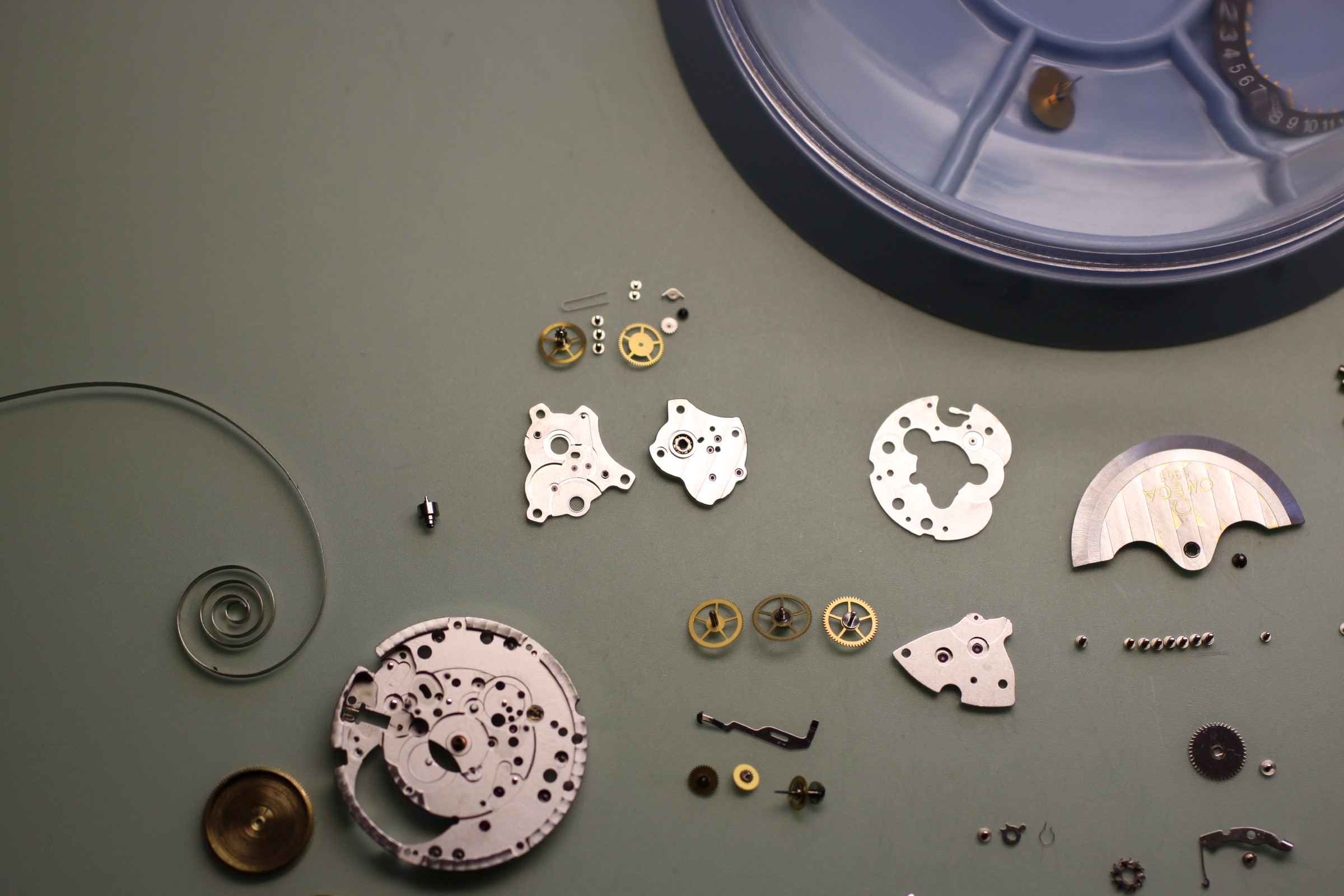
The movement components before cleaning in the cleaning machine and inspection under the microscope:
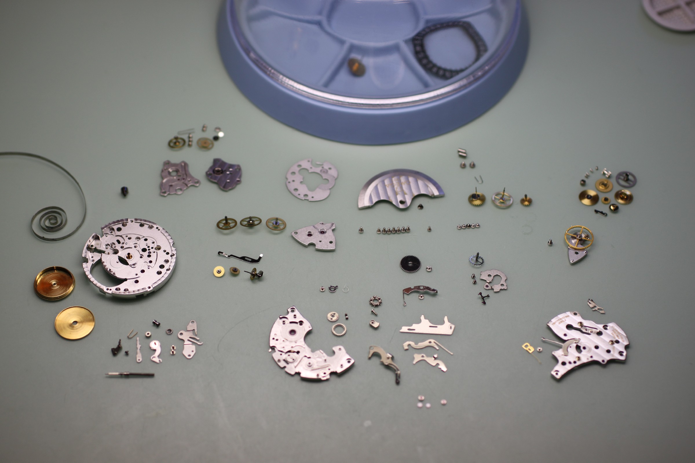
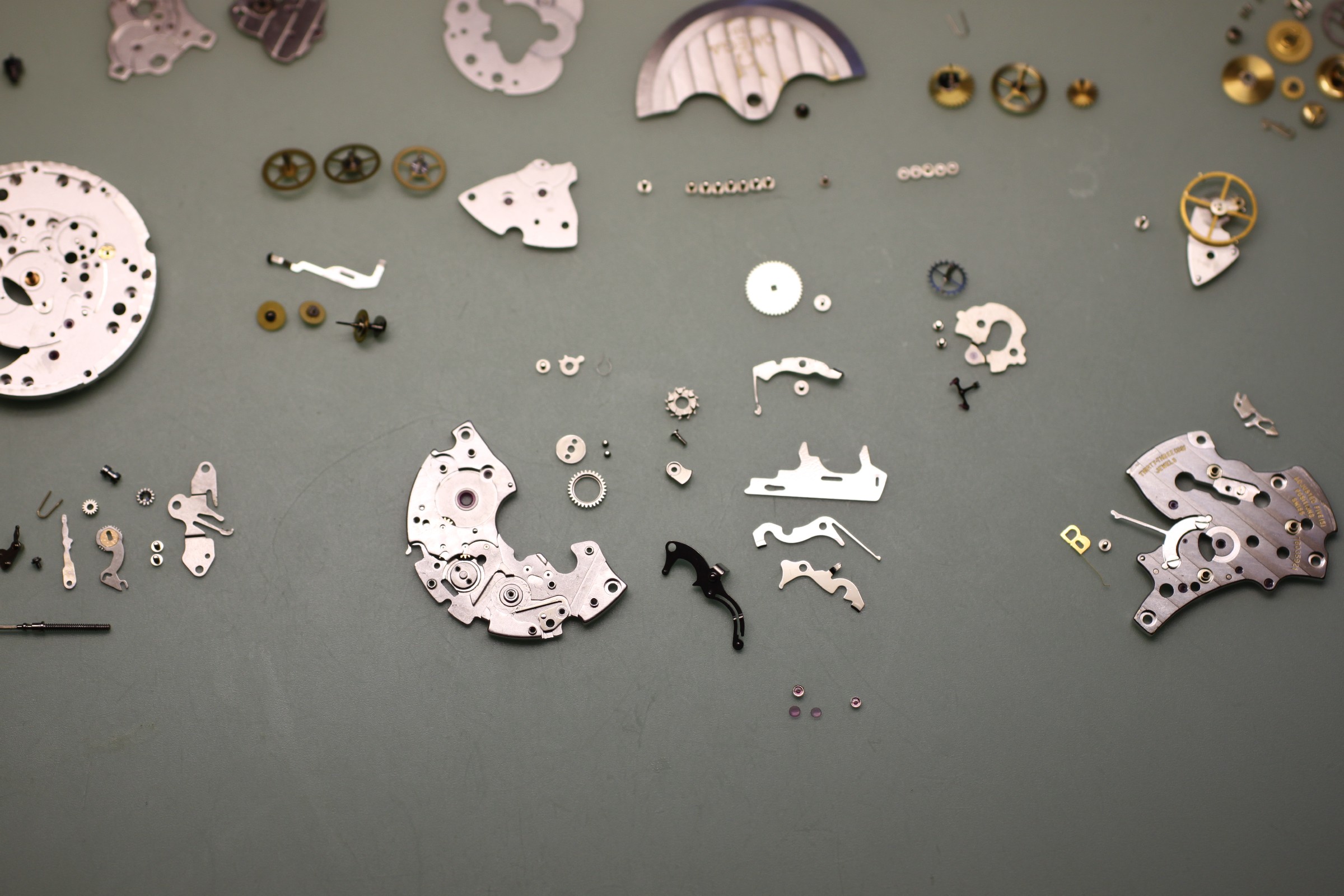
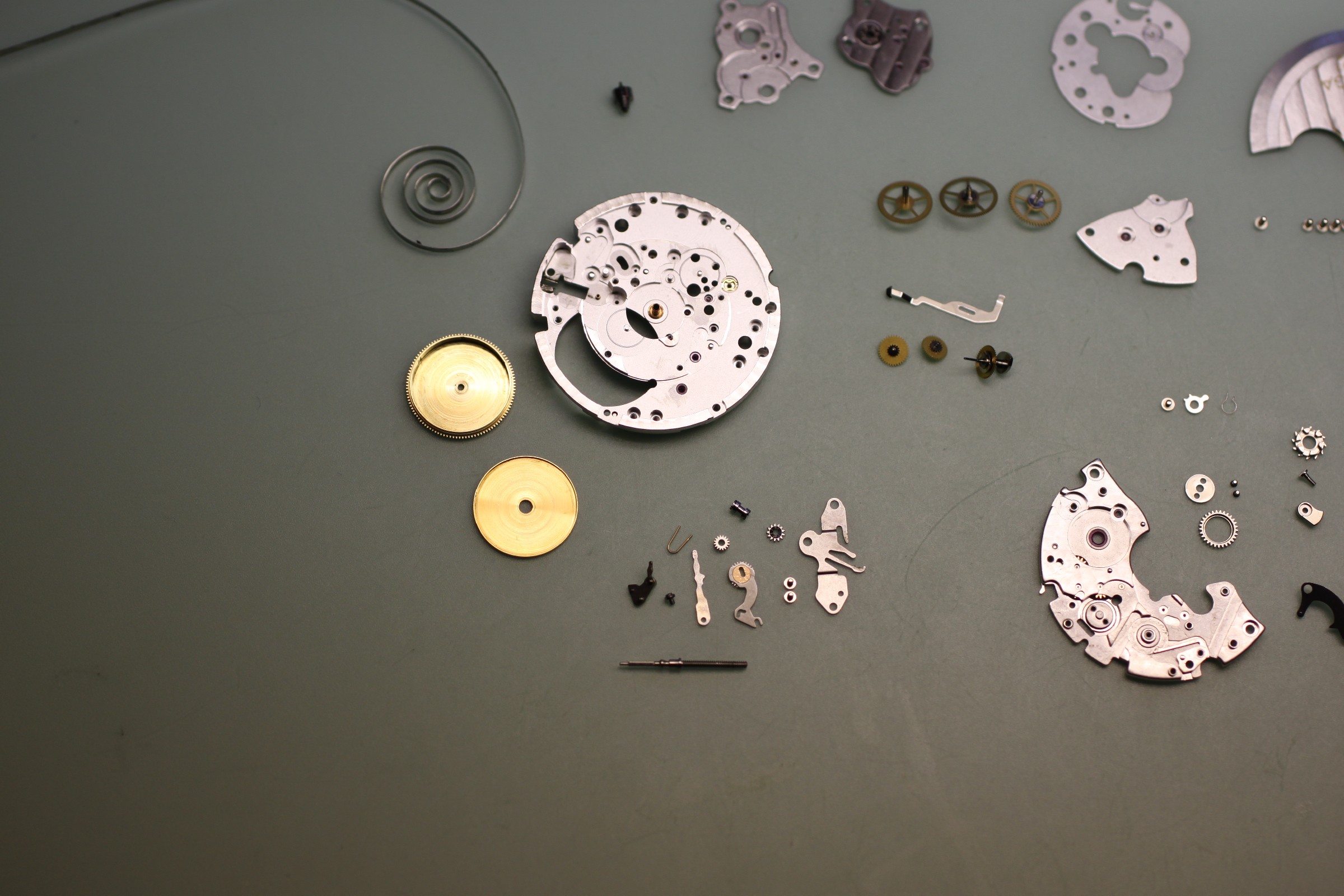
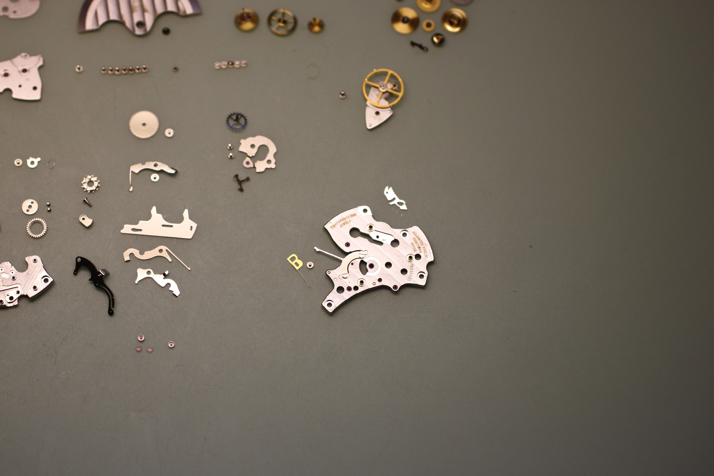
Checking the balance spring is among the final steps. For this, the balance and shock protection are fitted to the otherwise bare mainplate. This guarantees the best view from every direction. In this case, the flatness of the spring needed a minimal correction.
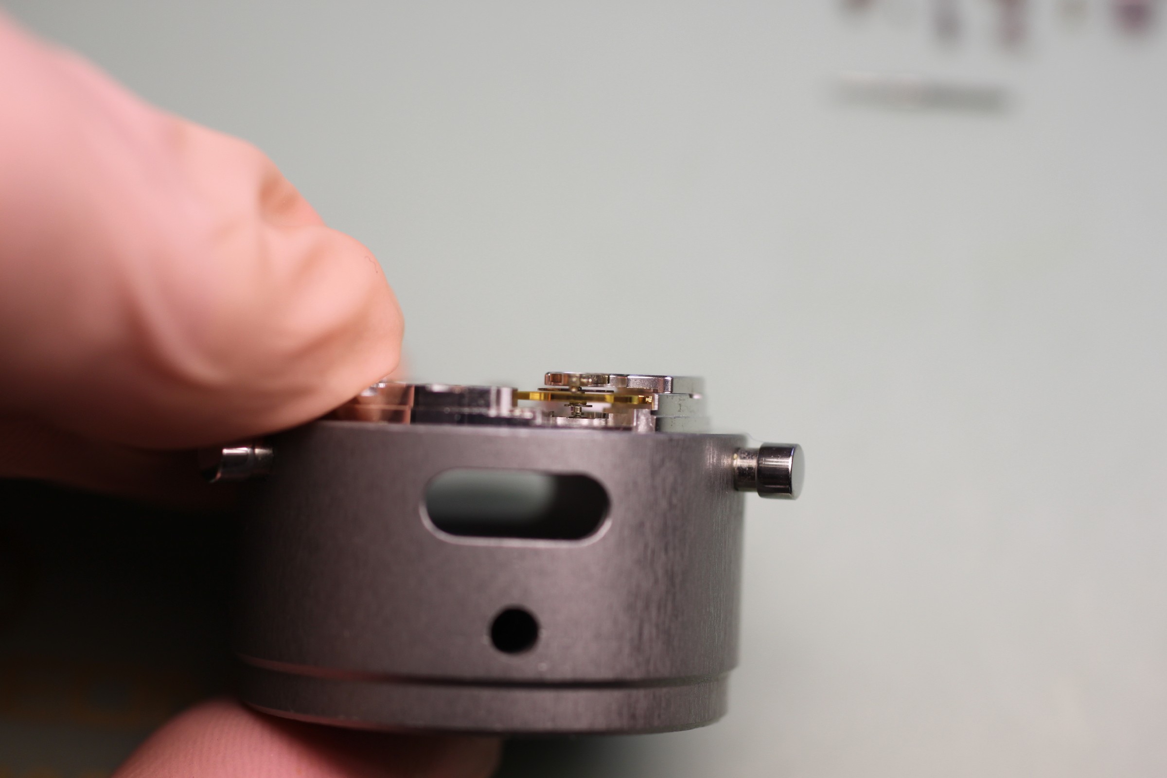
The shock protection is then removed and cleaned before the complete movement goes into the cleaning machine.
Assembly
Assembly of the movement is brisk but nevertheless precise. As far as possible, all faults have already been corrected during disassembly. This ensures that the movement spends as little time as possible on the workbench, keeping exposure to dust as brief as possible. Before assembly, the bench should be briefly wiped with a damp cloth.
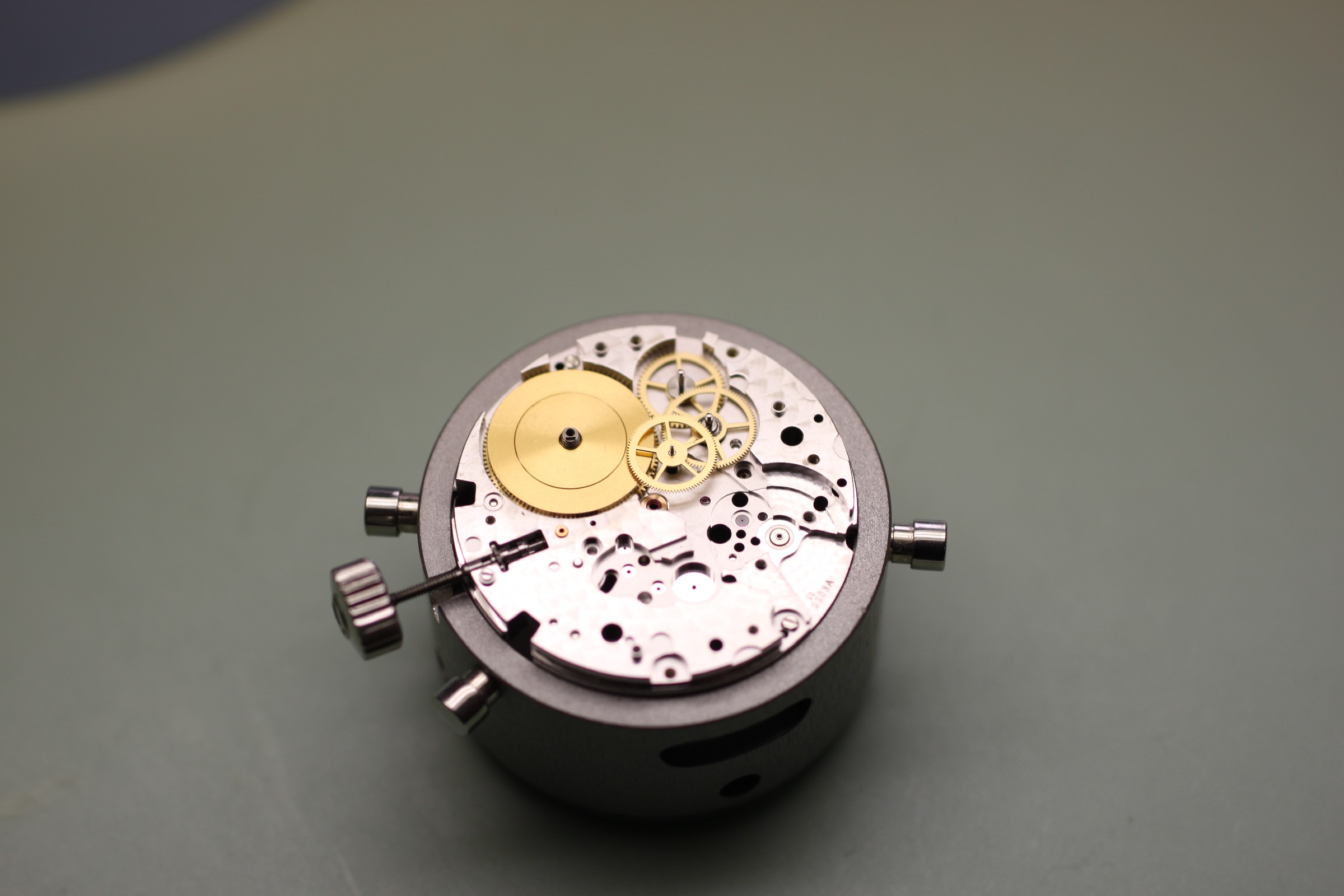
It is important when lubricating the three wheels beneath the barrel bridge to add enough HP1300 to the bearings for the clearly visible ring of lubricant in the photograph to form. Too little lubricant rapidly causes the wheels to seize, requiring another complete repair.
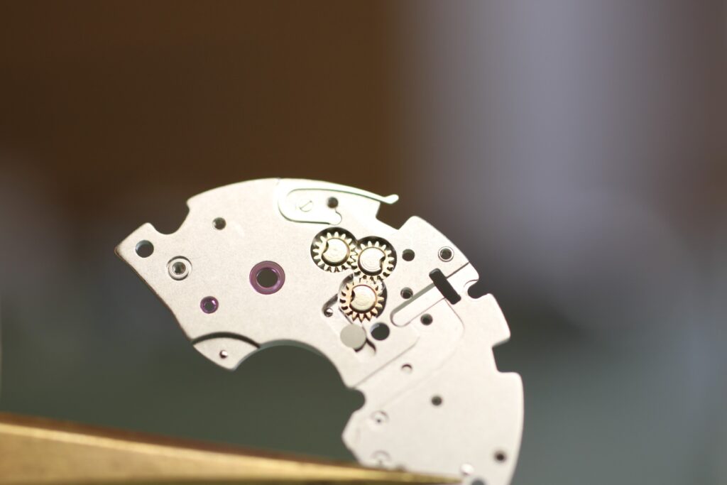
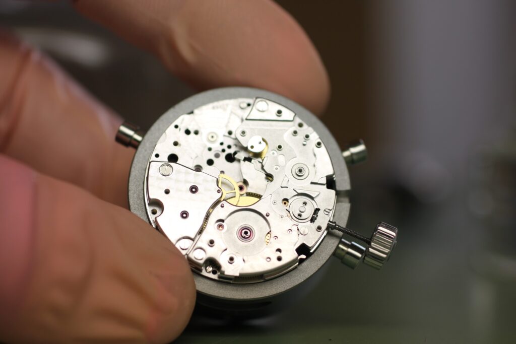
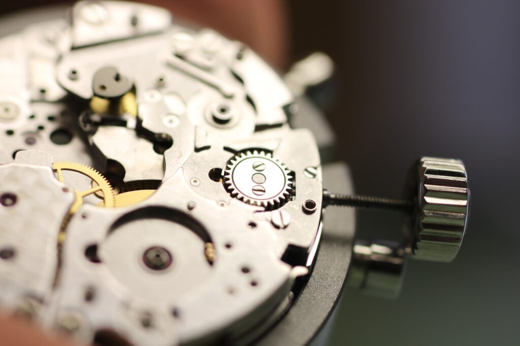
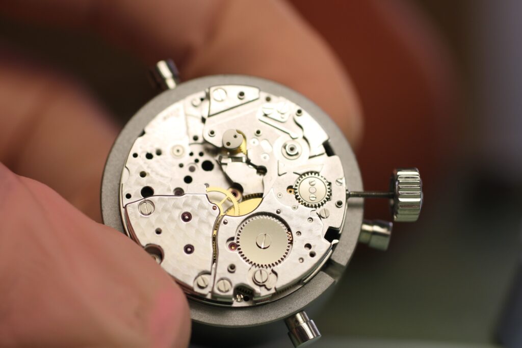
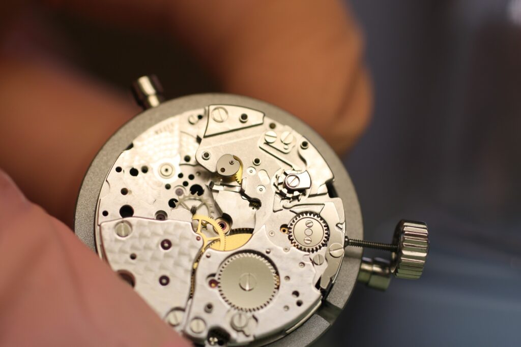
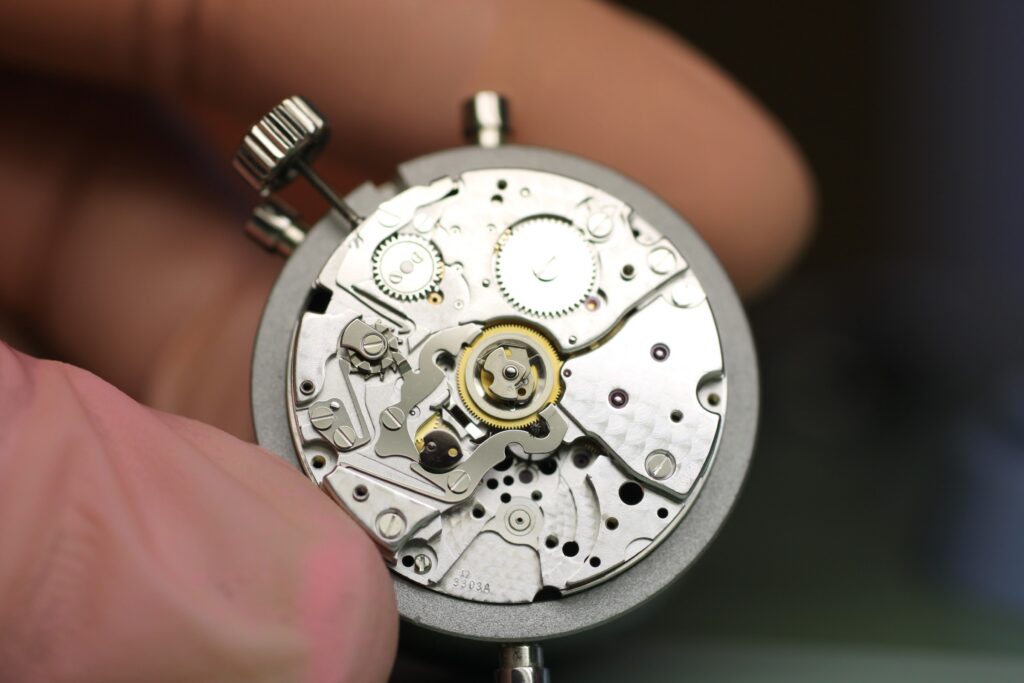
The hammers shown should also receive epilame treatment alongside the pallet stones, escape wheel and cap jewels. For many years, however, we have consistently treated the entire movement except for a small number of parts, as this gives significantly better oil retention.
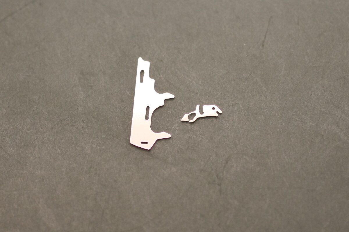
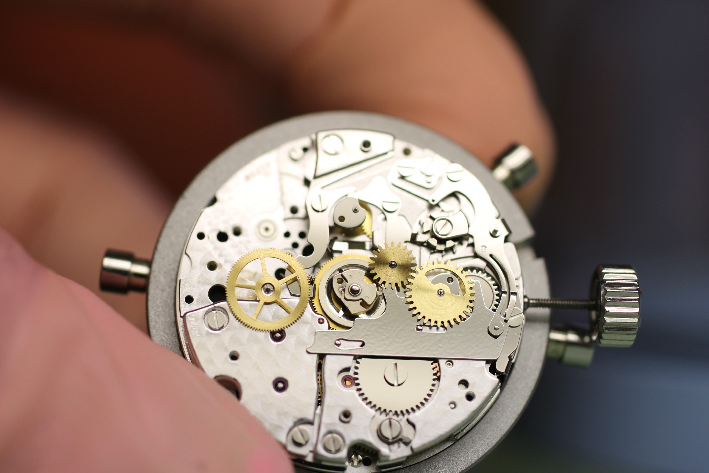
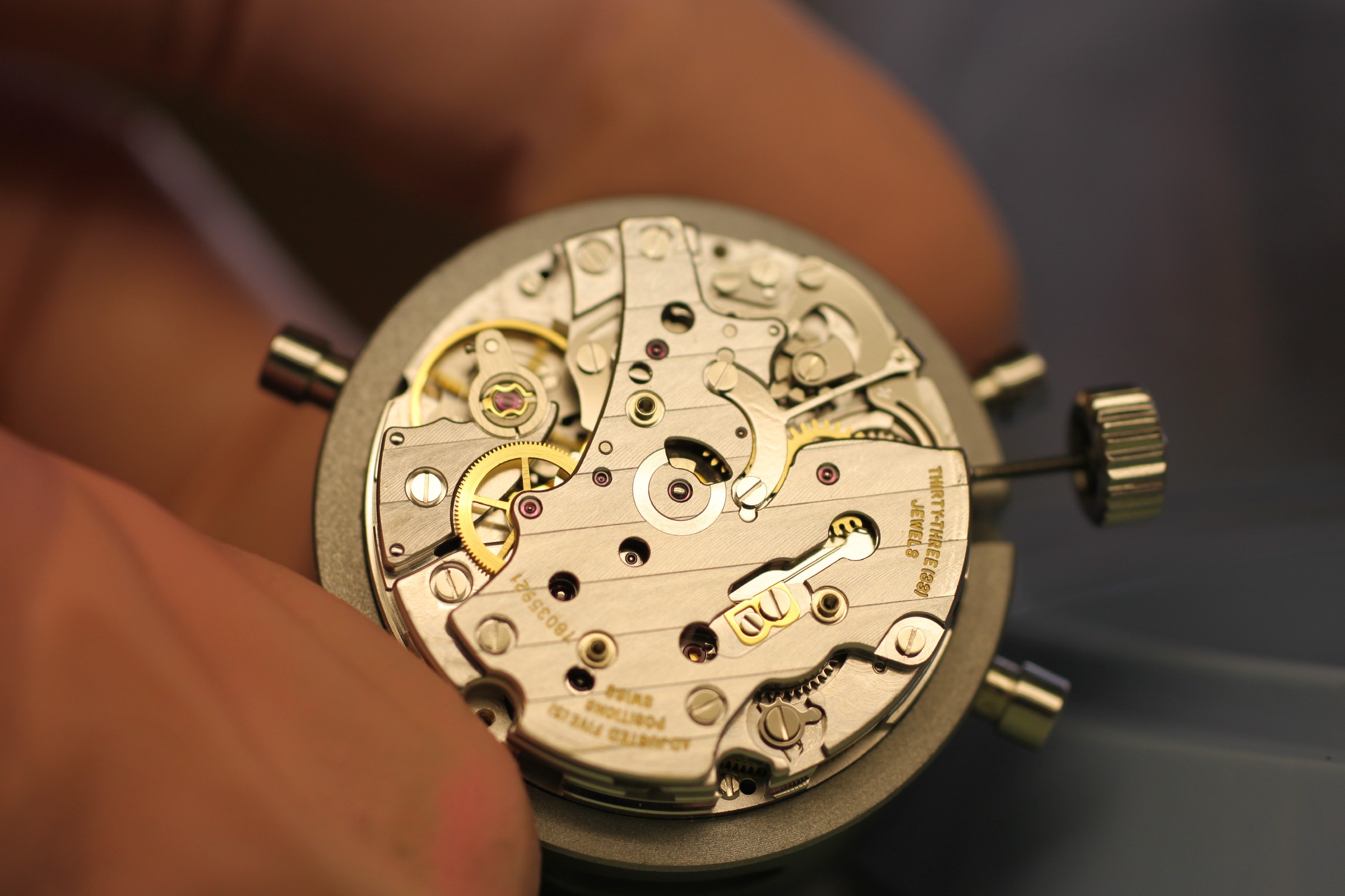
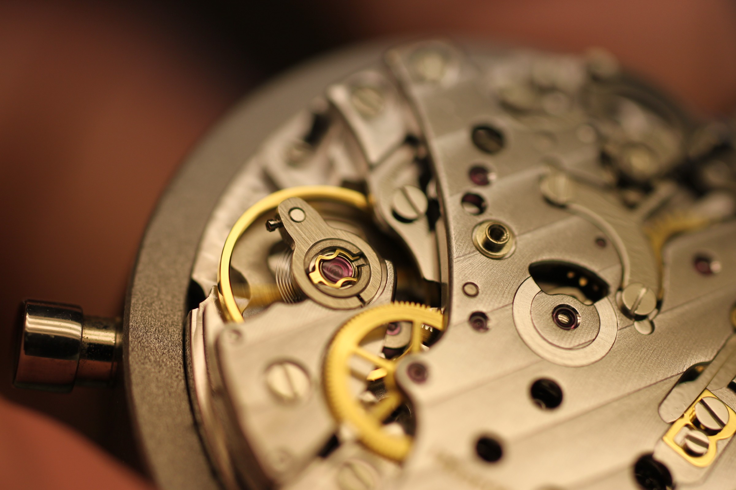
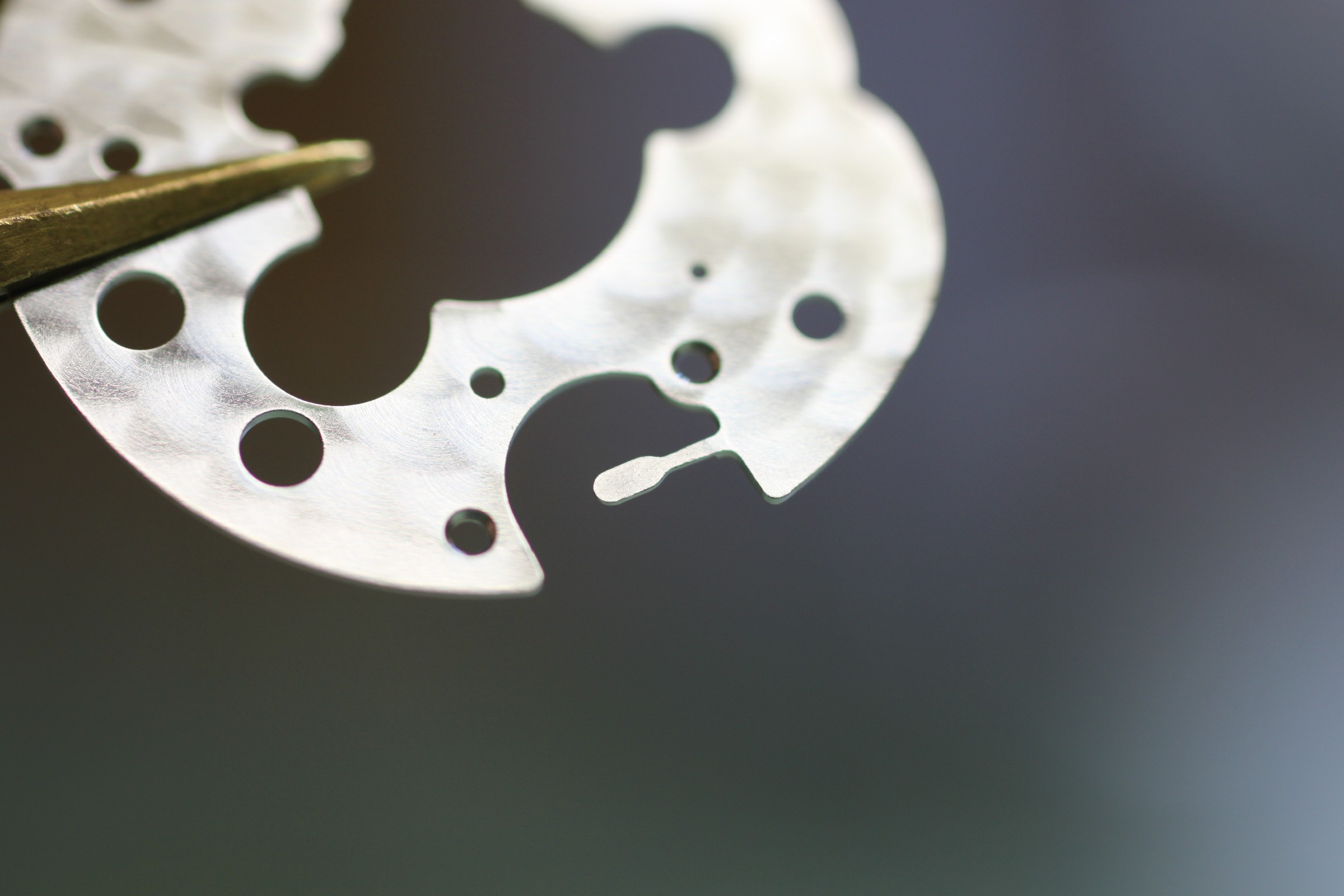
The small arm on the date bridge occasionally needs straightening. It rests on the date quick-set wheel and its contact pressure determines how quickly the wheel engages with the date disc when quick-setting through the crown.
If the tension is too weak, the crown must be turned forwards several revolutions before the date advances by one day.
If the tension is too strong, the date jumper cannot exert enough force during the jump to push the quick-set wheel aside – , occasionally causing an unclean date change. This can be checked by advancing the date manually just to the point of self-actuation and observing whether the force is sufficient to push the quick-set wheel aside.
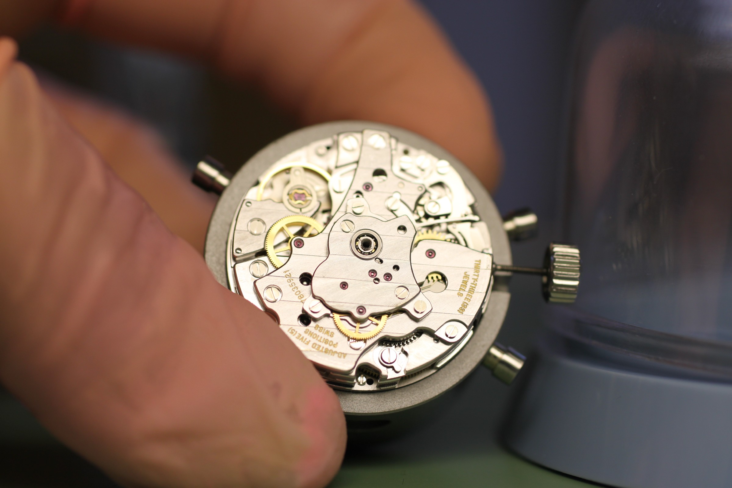
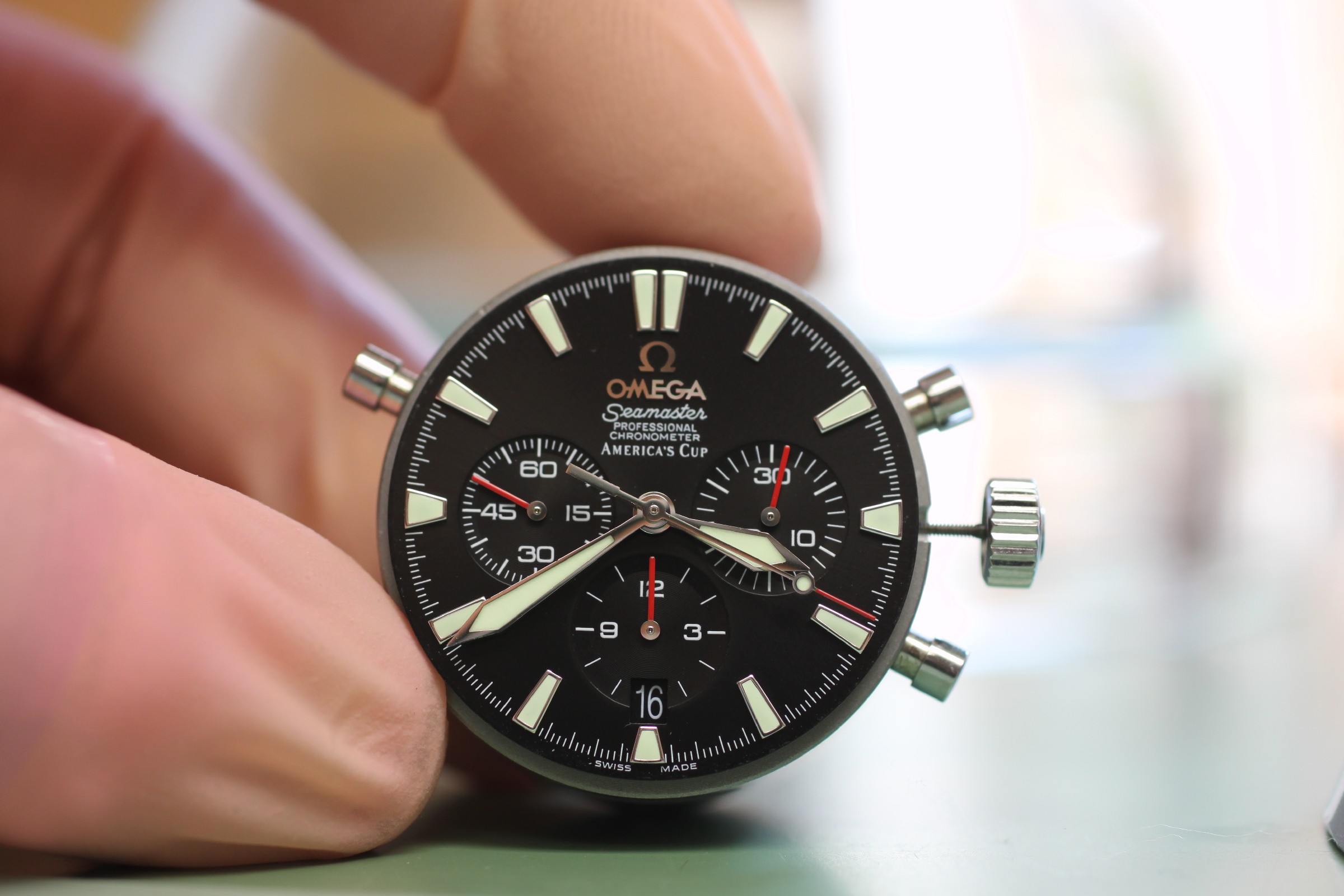
After fitting the hands, all chronograph functions are checked again. Meanwhile, the case has been restored and cleaned. The movement can now be cased up as usual, and the automatic winding, power reserve and rate checks performed.
The final result: